Lincoln distributed optical receiver array

a distributed optical receiver and receiver array technology, applied in the direction of electromagnetic transmission, electrical equipment, transmission, etc., can solve the problems of low reception optical power density of some free-space signals, unlikely candidates, cost and complexity of constructing and maintaining such devices, etc., to achieve accurate signal acquisition and tracking, and facilitate operation

Inactive Publication Date: 2005-08-04
MASSACHUSETTS INST OF TECH
View PDF4 Cites 9 Cited by
  • Summary
  • Abstract
  • Description
  • Claims
  • Application Information

AI Technical Summary

Benefits of technology

[0009] In order to collect light from the remote source, the receiver generally includes an adjustable mount. The mount is used to steer one or more of the elements of the optical detector array, thereby aiming them toward the remote source. To facilitate operation and to ensure accurate signal acquisition and tracking, the adjustable mount can be remotely controlled.

Problems solved by technology

Unfortunately, the received optical power densities for some free-space signals are extremely low.
The challenge for an optical receiver is to collect enough of the incident photons to detect and demodulate the transmitted signal.
This alternative, however, is an unlikely candidate due to the limited number of telescopes and the excessive cost and complexity of constructing and maintaining such devices.
Further complicating the detection of extremely low power optical communications signals is interference due to background light sources such as the sun, the moon, and planets.
In particular, these background light sources causes noise within an optical receiver.
These, however, would suffer due to their limited optical sensitivity values (e.g., the minimum number of photons to produce an electrical response) considering the low power-levels and interference sources.
Additionally, as the output signals from several of these light detectors are combined, the noise contributions also combine, tending to further reduce the detection sensitivity of the receiver.

Method used


Image

  • Lincoln distributed optical receiver array
  • Lincoln distributed optical receiver array
  • Lincoln distributed optical receiver array

Examples


Embodiment Construction

[0027] A description of preferred embodiments of the invention follows.

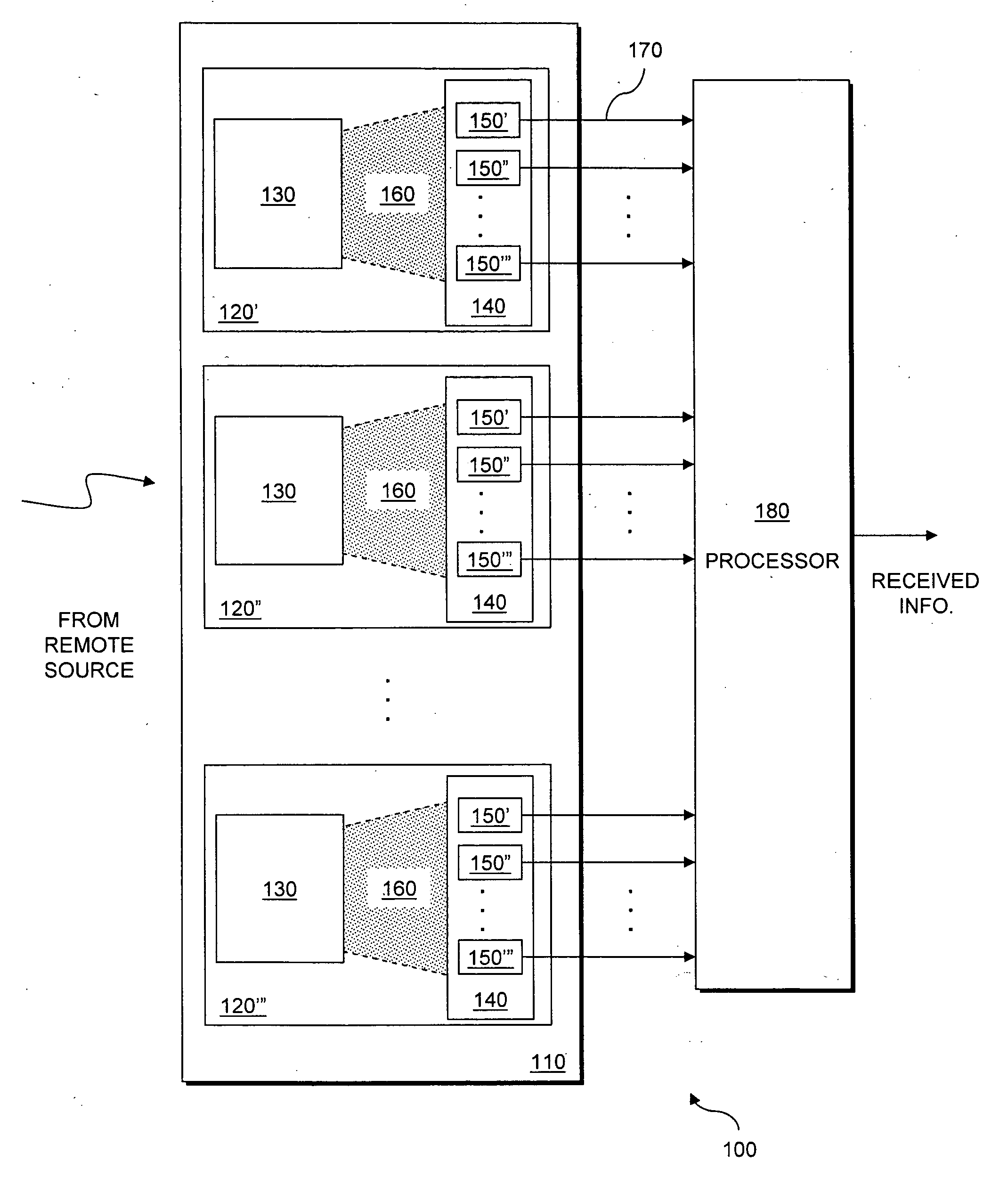
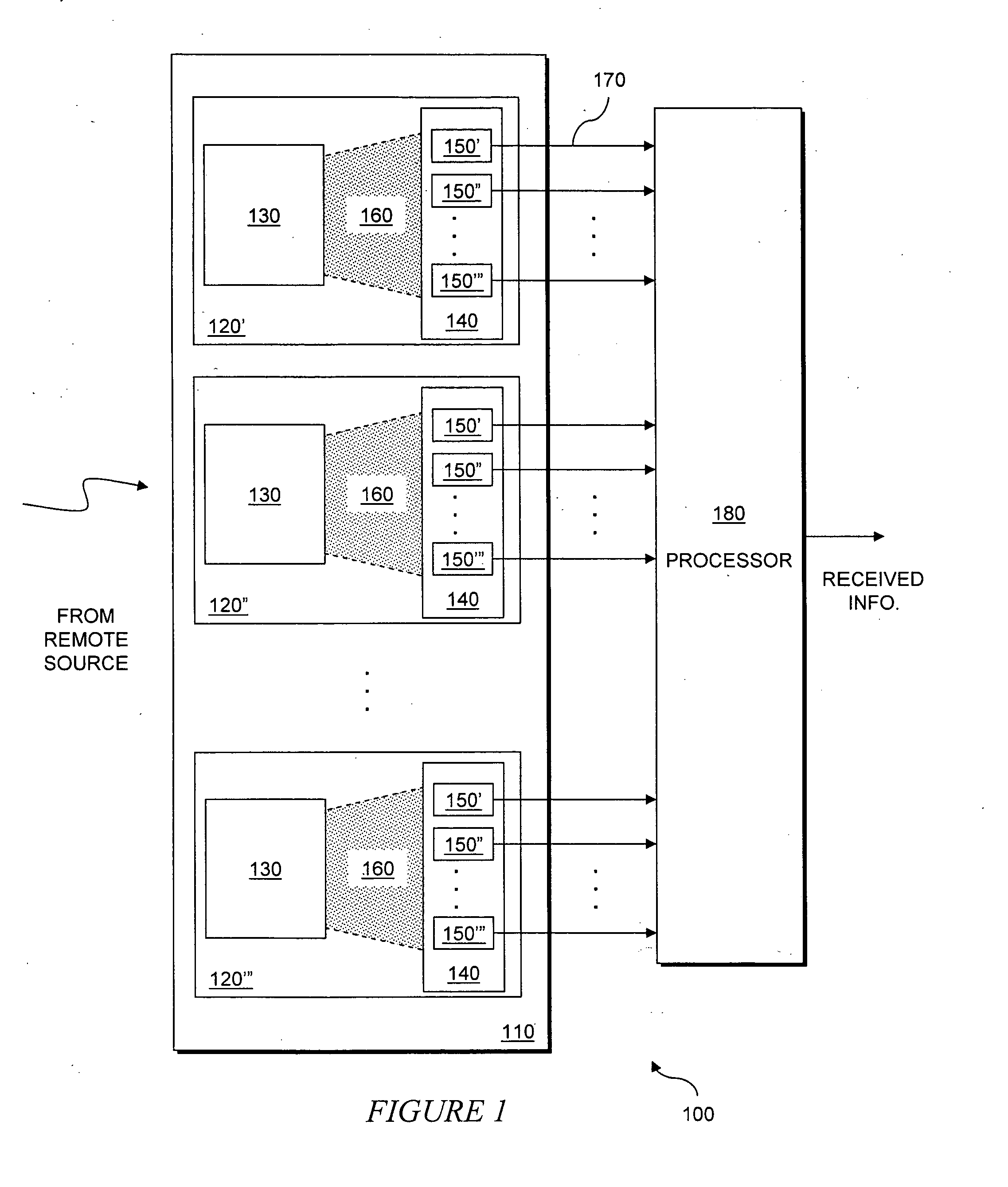
[0028] The present invention provides an array of modestly sized telescopes, each adapted to include an array of photon counting detectors. The resulting array of arrays yields an optical receiver that is well adapted for receiving extremely low power communication signals.

[0029] A schematic representation of an optical communications receiver is illustrated in FIG. 1. The optical communications receiver 100 includes an optical array 110 having a number of spatially-separated optical detectors 120. The optical array 150″, 150′″ (generally 150). The optical system 130 collects a portion of light received from the remote source and directs it toward the light-sensing array 140. A shaded region 160 represents the light directed from the optical system 130 to the light-sensing array 140. Notably, the dimensions of the different components are not necessarily drawn to scale. For example, the optical system 130 may b...


PUM


Abstract

An array of spatially-separated optical detectors is configured to receive a free-space optical communication signal from a remote source. Each optical detector of the array includes an optical system and an array of light sensors. The optical system collects a portion of light received from the remote source and directs it toward the array of light sensors. The array of light sensors, in turn, converts the collected portion of light to one or more electrical, detected signals corresponding to the collected portion of light. A processor is coupled to the array of spatially-separated optical detectors, receiving the detected signals and combining the received signals to obtain information borne by the received optical communication signal.

Description

GOVERNMENT SUPPORT [0001] The invention was supported, in whole or in part, by a grant F19628-00-C-0002 from NASA. The Government has certain rights in the invention.BACKGROUND OF THE INVENTION [0002] Free-space optical communications are being pursued in numerous applications, from terrestrial communications links between buildings or towns, to space communications links. Some of the advantages offered by free-space optical communications include an extremely narrow beamwidth to substantially reduce spreading loss compared to other Radio Frequency (RF) communication alternatives. Additionally, optical communications links tend to occupy less space, and utilize less mass and power compared to other RF communication alternatives. For at least these advantages, optical communications links will figure prominently in future space exploration. These communications links will include interplanetary communications links required to support exploratory missions to Mars and other planets. A...

Claims


Application Information

Patent Timeline
Patent Type & Authority Applications(United States)
IPC IPC(8): H04B10/06H04B10/10
CPCH04B10/1121
Inventor BONDURANT, ROY S.BOROSON, DON M.MURPHY, DANIEL V.
Owner MASSACHUSETTS INST OF TECH
Why Eureka
Try Eureka