Method of and apparatus for a multi-stage boundary layer engine and process cell

a technology of boundary layer engine and process cell, which is applied in the direction of air-flow influencers, marine propulsion, vessel construction, etc., can solve the problems of affecting the efficiency of continuous and/or impulse combustion turbine technology, affecting the efficiency and affecting the efficiency of the engine. , to achieve the effect of increasing the efficiency, reliability and flexibility of continuous and/or impulse combustion turbine technology

Inactive Publication Date: 2005-08-04
CENTRIPETAL DYNAMICS
View PDF10 Cites 89 Cited by
  • Summary
  • Abstract
  • Description
  • Claims
  • Application Information

AI Technical Summary

Benefits of technology

[0012] The present invention also provides a power generation system comprised of a series of stages which are formed or made of disc pack configurations. The different stages provide torque to a main output shaft. The stages preferably include compressor, turbine and / or vacuum stages. According to a preferred embodiment, the compressor stage feeds external combustors which provide power to the turbine. This power is then preferably fed into the vacuum stages. A vacuum source at the exhaust end of a water turbine can increase the efficiency of the turbine 3-4% for every cubic inch of water pulled.
[0022] Accordingly, it is the objective of the claimed invention to increase the efficiency, reliability and flexibility of continuous and / or impulse combustion turbine technology. The present invention may also be applied with like effect apart from present turbine processes and is intended for the broad purpose of producing power through a variety of mediums including gasoline, diesel, natural gas, biomass, methane, hydrogen, propane, liquid propane gas (LPG), steam, geothermal, solar hybrid, water, and the like.

Problems solved by technology

Fans, for example, are subject to significant stress as the fluid impacts the fan blades.
This can lead to damage of the blades, and can result in the introduction of foreign matter into the fluid.
In a closed-loop system, the foreign matter may be repeatedly injected into the engine compartment at high speed, and this can quickly result in catastrophic damage to both the blades and the engine itself.

Method used


Image

  • Method of and apparatus for a multi-stage boundary layer engine and process cell
  • Method of and apparatus for a multi-stage boundary layer engine and process cell
  • Method of and apparatus for a multi-stage boundary layer engine and process cell

Examples


Embodiment Construction

[0065] Reference will now be made in detail to preferred embodiments of the present invention, examples of which are illustrated in the accompanying drawings. Although this specification frequently makes reference to gases, liquids, and combinations thereof, it should be apparent to one skilled in the art that gases may be substituted for liquids, and liquids substituted for gases, without departing from the spirit or the scope of the present invention.

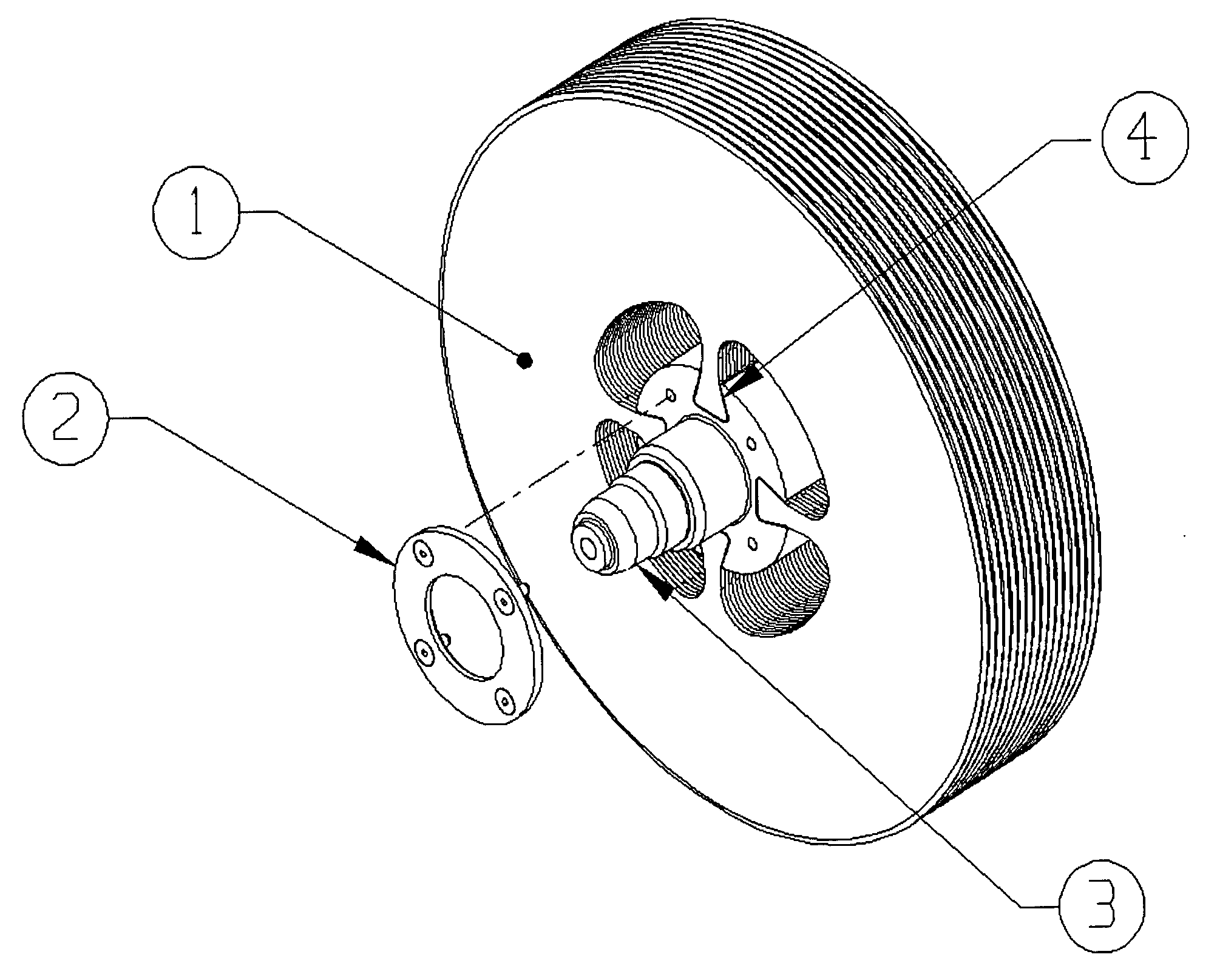
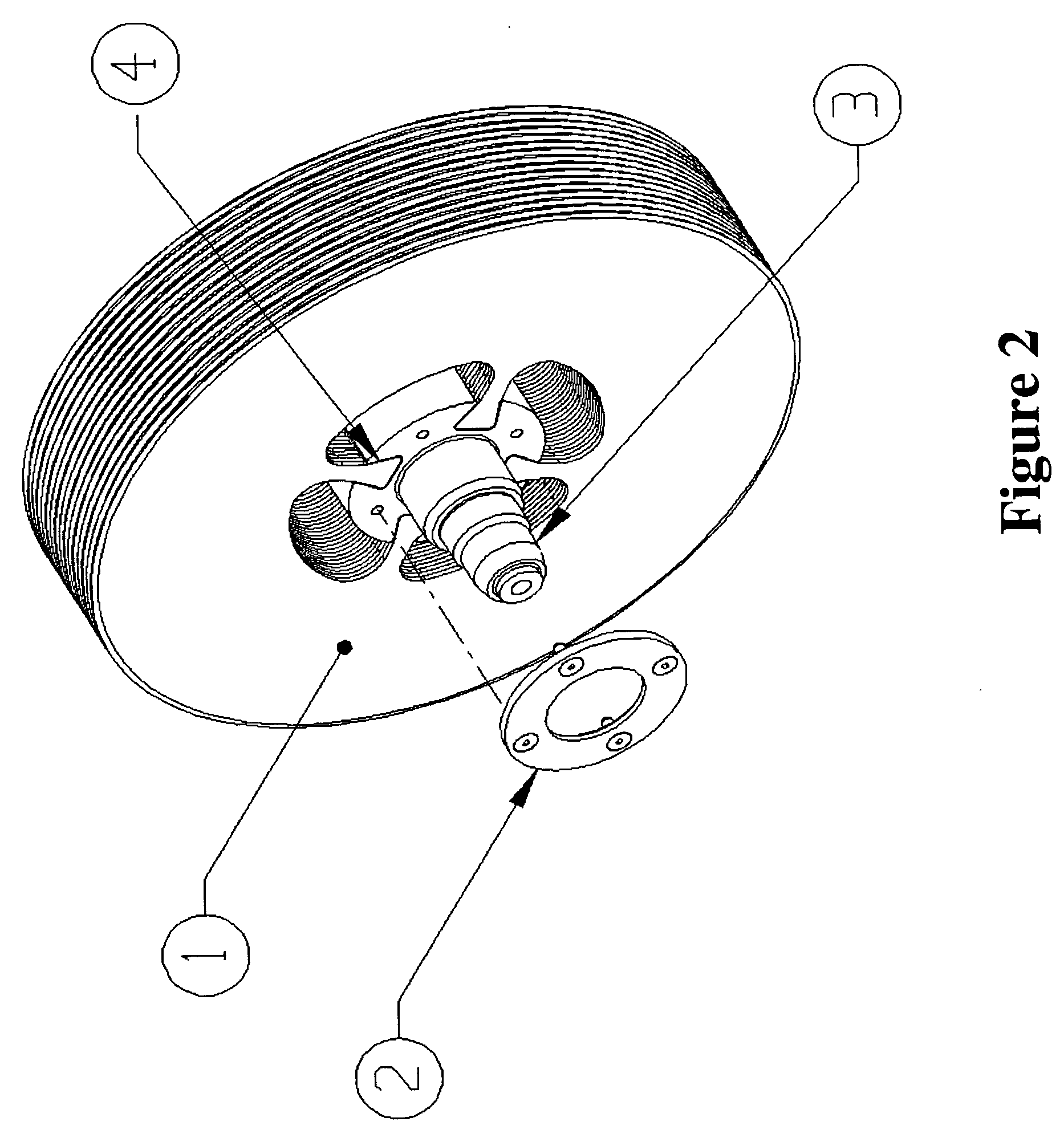
[0066]FIG. 2 is an illustration of a disk pack 1 mounted to a shaft 3 with a locking plate 2 using an internal dovetail configuration 4. The dovetail attachment means 4 reduces stress at the spoke interfaces when disk pack 1 is operated at high RPM's or at high temperatures compared to the prior art. It also provides more stability and increases the ability to statically and dynamically balance disc pack 1. Through this configuration, balancing can be accomplished by simply modifying locking plate 2 versus modifying disk pack 1. Alth...


PUM

PropertyMeasurementUnit
pressuresaaaaaaaaaa
shapeaaaaaaaaaa
poweraaaaaaaaaa

Abstract

A multi-staged boundary layer engine and process cell, (based on the effect known as adhesion and viscosity) which achieves high thermal efficiencies and high mechanical power output for use in the power generation, geothermal, energy recovery, solar, transportation, hydrogen production, desalinating water and hydroelectric fields. The design is novel with a dovetail attachment of the disc packs, allowing lower stress and allowing the use of next generation materials such as ceramics, composites and nanocomposites to improve the maximum temperature and the maximum RPM of the engine, thereby producing more horsepower and torque. In addition, this invention includes multi-stage vacuum, an external combustion chamber and condenser stages to improve the vortex flow through the primary disc pack cell. This engine will also encompass a closed loop cycle for ultimate efficiencies. This invention will also include the use of catalysts and / or electrical polarities applied to the disc pack and the disc pack / casing respectively to achieve low NOx and also to achieve process cell capability for applications such as desalinization and hydrogen generation.

Description

[0001] This application is related to, and claims the benefit of, Provisional U.S. Patent Application Ser. No. 60 / 415,239, filed Oct. 2, 2002, which is incorporated herein by reference in its entirety.FIELD OF THE INVENTION [0002] The present invention relates to the field of power generation, and more particularly it pertains to engines of a continuous and or impulse combustion type, which utilize boundary layer effects. The present invention can also act as part of a process, rather than simply performing a function. It also has the capability to act as a power generation unit and a process at the same time, (e.g. producing hydrogen, desalinating water, or the like). BACKGROUND OF THE INVENTION [0003] In 1903, Nikola Tesla engineered a type of steam turbine, for which he was granted U.S. Pat. No. 1,061,142 on May 6, 1913, and U.S. Pat. No. 1,061,206 on May 6, 1913, the teachings of which are incorporated herein in their entirety. This type of turbine is commonly referred to as a c...

Claims


Application Information

Patent Timeline
Patent Type & Authority Applications(United States)
IPC IPC(8): B63H9/02F01D1/36
CPCB82Y30/00F01D1/36Y02T50/672F05D2300/143F05D2300/21B33Y80/00Y02T50/60
Inventor HICKS, KENNETH
Owner CENTRIPETAL DYNAMICS
Why Eureka
Try Eureka