Rotor blade for a rotary machine

a rotary machine and rotor blade technology, applied in the field of rotor blades, can solve the problems of increasing stresses at the interface of the shroud airfoil, creeping of the airfoil, and creeping of parts of the shroud, so as to reduce the stress concentration factor, reduce surface stress, and reduce the effect of stress concentration factor

Active Publication Date: 2005-08-04
RTX CORP
View PDF12 Cites 62 Cited by
  • Summary
  • Abstract
  • Description
  • Claims
  • Application Information

AI Technical Summary

Benefits of technology

[0021] Another advantage is that a life of the rotor blade resulting from the level of concentrated stresses associated with the stress concentration factor caused by the transition zone beneath the beam and forward of the beam on the suction side of the airfoil by providing an offset ratio which is greater than one at those locations to reduce the stress concentration factor and by transferring a portion of the rotational loads acting on the wings to the beam to permit using a transition zone whose contour follows a portion of a circle or nearly circular configuration to provide more transition zone material along the pressure side of the airfoil adjacent the rear wing to reduce surface stresses in the pressure side of the airfoil.
[0022] In one embodiment, an advantage is the fatigue life resulting from the level of stresses in the rear transition zones adjacent the laterally thinner part of the airfoil which results from transferring a portion of the loads acting on the rear wings through the inverted T-section of the beam to the transition zone underneath the beam which has been contoured to provide an offset ratio which reduces the stress concentration factor as compared to a circular transition zone.

Problems solved by technology

These rotational loads increase stresses at the shroud airfoil interface because of the sudden change in cross-section of the material and at the root-disk interface of the rotor blade and the desk.
In addition, the mass of the shroud may cause creep of the airfoil and creep of portions of the shroud in a radial direction because of rotational forces generated under operative conditions.

Method used


Image

  • Rotor blade for a rotary machine
  • Rotor blade for a rotary machine
  • Rotor blade for a rotary machine

Examples


Embodiment Construction

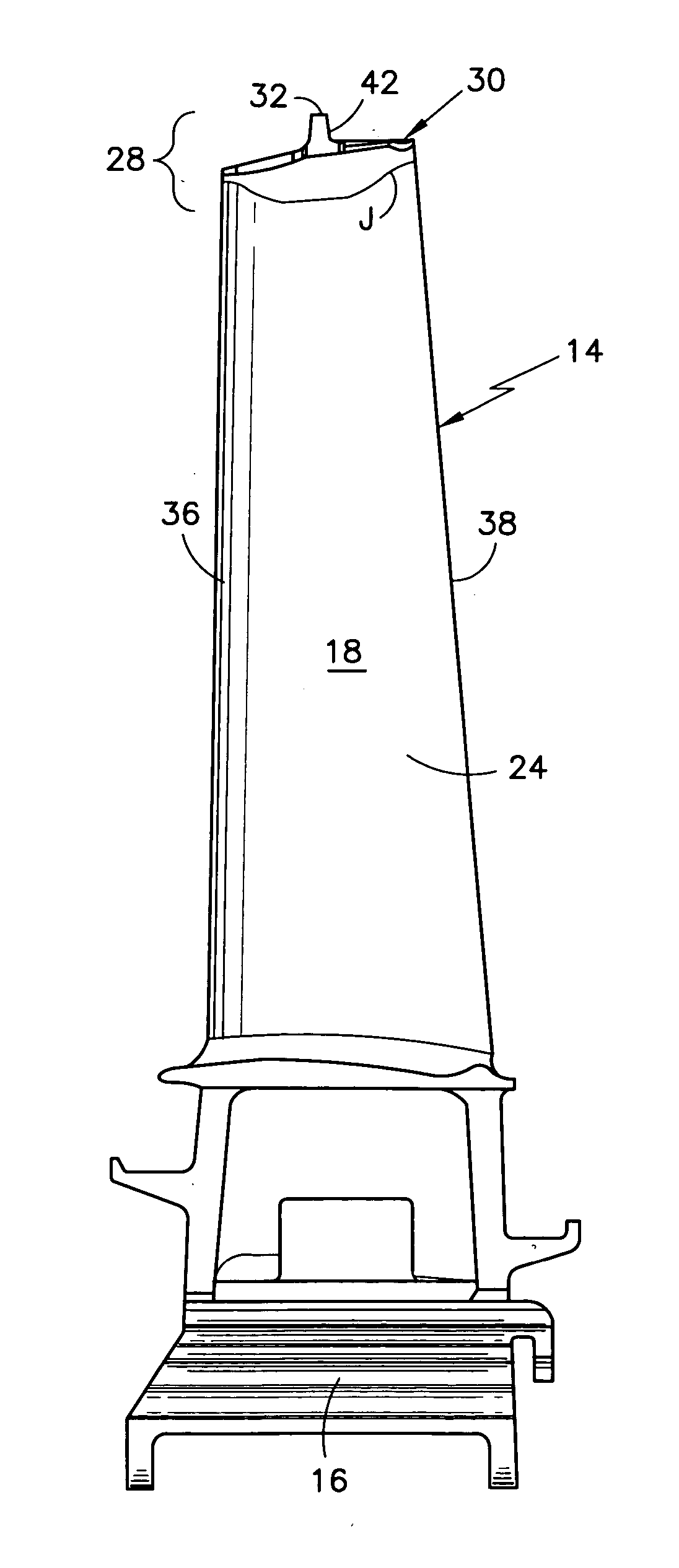
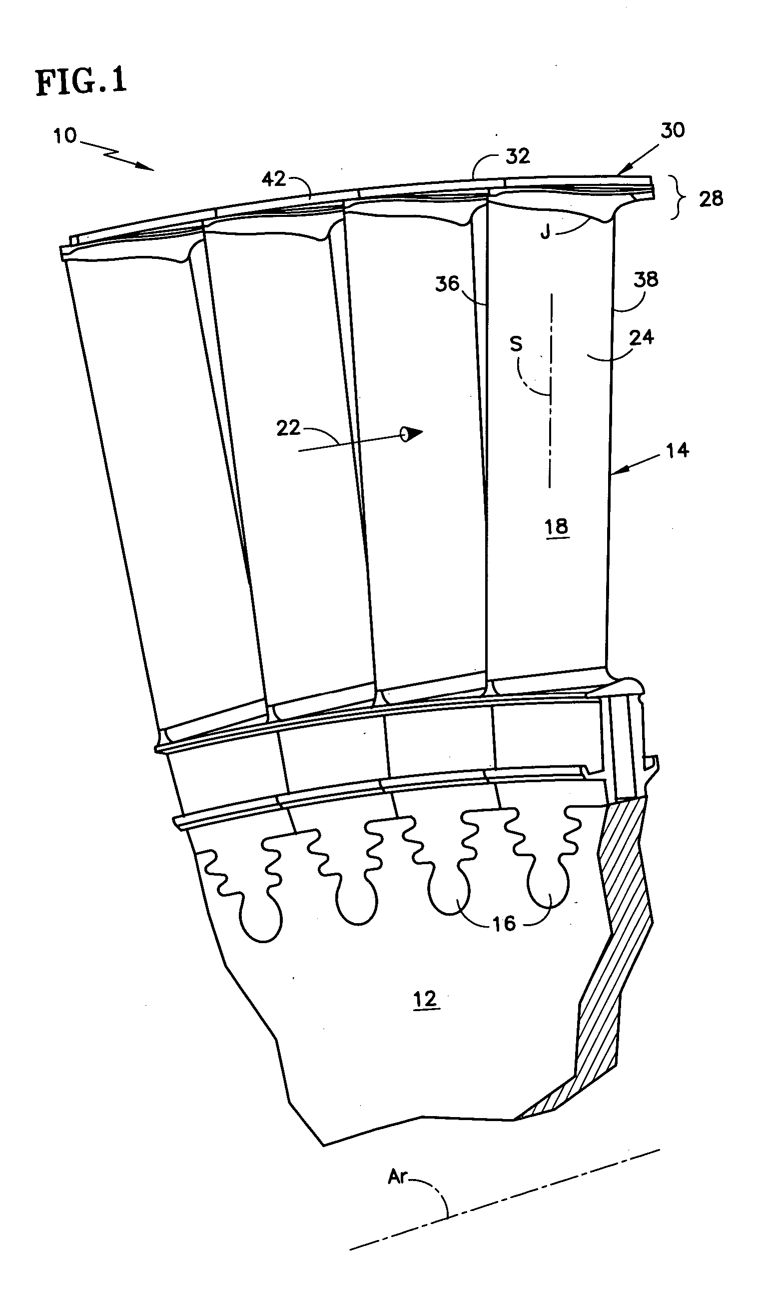
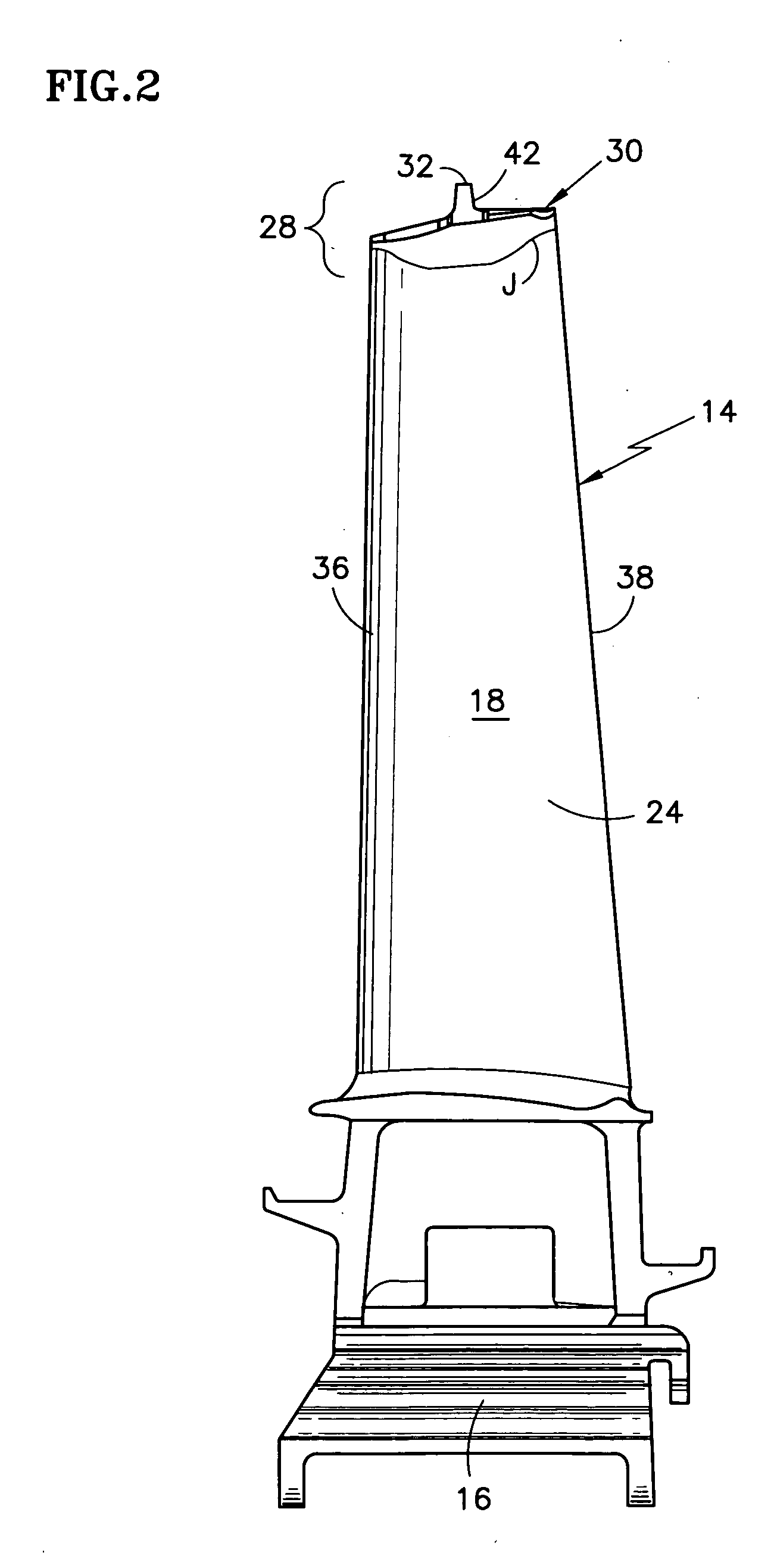
[0034]FIG. 1 is a simplified front elevation view of a rotor assembly 10 of a rotary machine having an axis Ar. The rotor assembly includes a rotating structure, as represented by the disk 12, and a plurality of outwardly extending rotor blades 14. Each rotor blade has a root 16 and an airfoil 18 being disposed about a spanwisely extending axis S, which is commonly called the stacking line S. The airfoil has a pressure side 24 and a suction side 26. A flowpath 22 for working medium gases extends through the rotor blades between the sides of the airfoil.

[0035] The rotor blade has a tip region 28 having a tip shroud 30. The tip shroud includes a seal land 32 which is a surface having a radius of curvature about the axis Ar. The tip shroud has a transition zone 34 which extends from the sides 24, 26 of the airfoil, as represented by the pressure side. The transition zone includes part of a flowpath surface which extends from a tangent to the pressure side of the airfoil along a juncti...


PUM


Abstract

A rotor blade having a wing and beam construction for a tip shroud is disclosed. Various construction details are developed for providing a transition zone that extends from the suction side and pressure side of the airfoil to provide a flow path surface of the shroud. In one detailed embodiment, the transition zone over substantially all of its extent between the leading edge region and the trailing edge region is contoured to extend to the sides of the wings to provide a spanwise taper that extends to the side of the wing.

Description

TECHNICAL FIELD [0001] This invention relates to rotor blades of the type used in industrial gas turbine engines, and more specifically, trout for the tip region of such a rotor blade. BACKGROUND OF THE INVENTION [0002] Gas turbine engines for aircraft have rotor blades that typically are smaller than rotor blades used in, for example, the turbine of an industrial gas turbine that employs steam as a working medium. [0003] The rotor assembly employs such blades with a rotating structure, such as a rotor disk, having an axis of rotation and a plurality of outwardly extending blades. Each blade is disposed about a spanwise axis that extends radially. Generally, the spanwise axis is a radial line referred to as the stacking line which extends outwardly on a radius from the axis of the rotor blade. The rotor blade has a base, commonly called a root, which engages the rotating structure at the inner end of the blade. [0004] The rotor blades each have an airfoil which extends outwardly fro...

Claims


Application Information

Patent Timeline
Patent Type & Authority Applications(United States)
IPC IPC(8): F01D5/14F01D5/20F01D11/08
CPCF01D5/143F01D5/147F01D5/225F01D11/08F05D2260/94Y10S416/02Y02T50/671Y02T50/673F05D2250/232F05D2250/70F05D2250/71F05D2260/941Y02T50/60
Inventor DUBE, BRYAN P.GRAY, ERIC D.
Owner RTX CORP
Why Eureka
Try Eureka