Controlled direct liquid injection vapor feed for a DMFC

a technology of direct oxidation fuel cells and liquid injection vapor feed, which is applied in the direction of fuel cell details, cell components, electrochemical generators, etc., can solve the problems of high power applications, difficult to provide in a tightly volume-limited dmfc technology platform, and limited reformer based systems. , to achieve the effect of simple and effective carbon dioxide releas

Inactive Publication Date: 2005-08-04
MTI MICROFUEL CELLS
View PDF56 Cites 43 Cited by
  • Summary
  • Abstract
  • Description
  • Claims
  • Application Information

AI Technical Summary

Benefits of technology

[0025] The disadvantages of prior techniques are overcome by the present invention, which provides a unique, passive direct oxidation fuel cell system, which includes the following features: 1) the fuel cell system carries a high concentration fuel, including the option of neat methanol; 2) the fuel cell system limits the delivery rate of the fuel so that the fuel substance is consumed to large degree, typically 80%-90%, when it comes into contact with the anode face of the catalyzed membrane and mixes there with water provided internally from the cathode; 3) the fuel cell system of the present invention includes passive water management components for maintaining a balanced distribution of water in the cell, and 4) the fuel cell includes features and components for simple and effective carbon dioxide release from the anode chamber of the fuel cell.
[0026] In accordance with one aspect of the invention, an optimized water profile within the fuel cell is achieved by using water management elements to confine a substantial portion of the water of the fuel cell between the two diffusion layers, minimizing water loss or discharge from the fuel cell. This is accomplished using a water management component such as a hydrophobic microporous layer, or a water management film placed in intimate contact with the cathode catalyst, or with both anode and cathode catalyst layers, and applying sufficient compression to maintain effective uniform adhesion of such water management component to the catalyst layer even as liquid water builds up at the interface between the catalyst layer and said water management component, thus ensuring water back-flow from the cathode into the membrane.
[0029] The unique features of the present invention allow this optimized water distribution in the cell to be maintained, even when neat methanol is directly supplied from the fuel cartridge (or reservoir). The present invention enables to deliver the neat fuel at the appropriate rate into the anode chamber as required to achieve an optimized, low concentration in contact with the anode face of the catalyzed membrane, to which face water is effectively supplied internally across the membrane from the cathode. As noted herein, the desirable reaction at the anode is process (1), which involves one molecule of methanol and one molecule of water, and in order for this reaction to proceed the rate of methanol supply has to be controlled such that a sufficient amount of water that is needed for process (1) to occur, flows back from the cathode into the anode chamber.

Problems solved by technology

However, because fuel processing is complex and generally requires components which occupy significant volume, reformer based systems are presently limited to comparatively large, high power applications.
In addition, it might lead to the generation of a hazardous anode product (formaldehyde).
Typically, it has been difficult to provide in a tightly volume-limited DMFC technology platform, the high ratio water / methanol mixture at the anode catalyst that ensures effective and exclusive anode process (1).
The disadvantage of Class A systems is that while neat methanol can be carried in the cartridge, the system suffers from excessive complexity due to the pumping and recirculation components which result in significant parasitic power losses and increase in system volume.
Such power losses can be particularly severe, relative to fuel cell power output, in the case of small scale power sources.
The problem with this approach is that it requires that the system carries a significant amount of water together with the methanol in the cartridge.
Carrying a methanol / water mix in the reservoir or cartridge, of a composition well under 100% methanol, results in a significant penalty in energy density of the power pack.
However, the possibility of supply of highly concentrated methanol, including 100% methanol, directly from a reservoir into the anode compartment, has not been considered practical without, at the same time, supplying water as well into the anode compartment by either collecting it from the cathode and externally pumping it back or, alternatively, directly feeding water from a reservoir of water-diluted methanol.
In other words, the combination “Passive DMFC System” and “Neat Methanol Supply to the Anode” has not been considered feasible, as this has been fully expected to result in significant loss of methanol flowing across the membrane (significant methanol “cross-over”) and / or in an anode process different than (1).
However, space in such small devices is limited such that the form factors for any powering unit for use in connection with such devices is a critical design feature.

Method used


Image

  • Controlled direct liquid injection vapor feed for a DMFC
  • Controlled direct liquid injection vapor feed for a DMFC
  • Controlled direct liquid injection vapor feed for a DMFC

Examples


Embodiment Construction

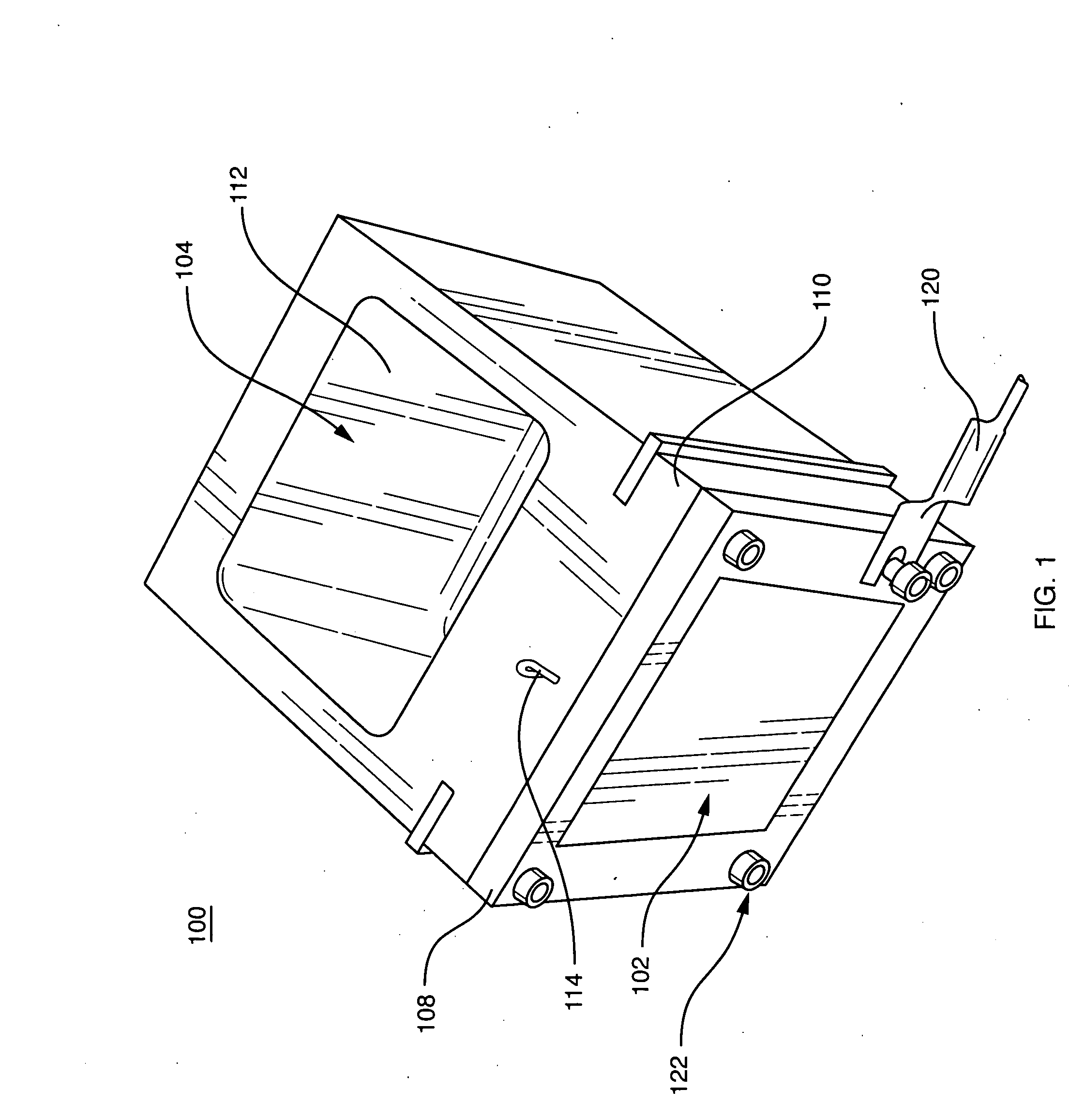
[0050]FIG. 1 illustrates a direct oxidation fuel cell system 100 that includes a direct oxidation fuel cell 102 in conjunction with a fuel reservoir 104. The fuel cell 102 is held together by a frame 108 and it is encapsulated within a plastic exterior housing 110, which may be comprised of a plastic. The fuel reservoir 104 has a recess 112 into which fuel or a fuel cartridge is inserted to begin the delivery of fuel to the anode portion of the fuel cell as will be discussed in further detail hereinafter. The anode portion of the fuel cell has no liquid outlet. In FIG. 1, the active surface of the cathode is located on the aspect corresponding to the front face of the cell as shown. The anode current collection lead 114 is in ohmic contact with the anode current collector (hidden in FIG. 1) and can be connected with the cathode current collector lead 120 to form an electrical circuit and a load can be connected across the leads 114 and 120 to utilize the electricity produced by the ...


PUM

PropertyMeasurementUnit
thicknessaaaaaaaaaa
thicknessesaaaaaaaaaa
thickaaaaaaaaaa

Abstract

A fuel cell system having a methanol vapor delivery component or film is provided. The component includes an evaporation pad. The evaporation pad is disposed within the fuel cell generally parallel to the anode diffusion layer, but with a vapor gap provided between the evaporation pad and the anode diffusion layer. A fuel delivery conduit having at least one injection port is provided through which liquid fuel is delivered from an associated source of highly concentrated fuel into the evaporation pad, at a controlled, adjustable rate. Multiple parallel liquid delivery points can also be provided. In order to ensure uniform delivery of fuel across the across the active area of the anode, one or more dispersion members are placed on the evaporation pad to effectively disperse the fuel laterally around each injection port.

Description

CROSS-REFERENCE TO RELATED APPLICATION [0001] The present application is a continuation-in-part of commonly assigned co-pending U.S. patent application Ser. No. 10 / 413,983, which was filed on Apr. 15, 2003, by Ren et al., for a DIRECT OXIDATION FUEL CELL OPERATING WITH DIRECT FEED OF CONCENTRATED FUEL UNDER PASSIVE WATER MANAGEMENT, and is hereby incorporated herein by reference.BACKGROUND OF THE INVENTION [0002] 1. Field of the Invention [0003] This invention relates generally to direct oxidation fuel cells, and more particularly, to fuel cells that operate with delivery of high concentration fuel and passive water management. [0004] 2. Background Information [0005] Fuel cells are devices in which an electrochemical reaction involving a fuel molecule is used to generate electricity. A variety of compounds may be suited for use as a fuel depending upon the specific nature of the cell. Organic compounds, such as methanol or natural gas, are attractive fuel choices due to the their hi...

Claims


Application Information

Patent Timeline
Patent Type & Authority Applications(United States)
IPC IPC(8): H01M4/86H01M4/92H01M4/94H01M4/96H01M8/02H01M8/04H01M8/10
CPCH01M8/04171H01M8/04186H01M8/04291Y02E60/523H01M8/2455H01M8/2475H01M8/1011Y02E60/50
Inventor REN, XIAOMINGBECERRA, JUAN J.HIRSCH, ROBERT S.GOTTESFELD, SHIMSHONKOVACS, FRANK W.SHUFON, KEVIN J.
Owner MTI MICROFUEL CELLS
Why Eureka
Try Eureka