
Base cloth for coated airbag and method for manufacturing the same

a technology of airbag base cloth and base fabric, which is applied in the direction of weaving, pedestrian/occupant safety arrangement, vehicular safety arrangement, etc., can solve the problems of unsatisfactory fabric formed of fibers in point of reducing thickness, increasing the thickness of flexible fabrics, and achieving improved compactness and containability of coated base fabrics. achieve better coverage capability, reduce the fineness of filaments, and improve the effect of retaining flexibility

Inactive Publication Date: 2005-08-04
TORAY IND INC
View PDF5 Cites 20 Cited by
  • Summary
  • Abstract
  • Description
  • Claims
  • Application Information

AI Technical Summary

Benefits of technology

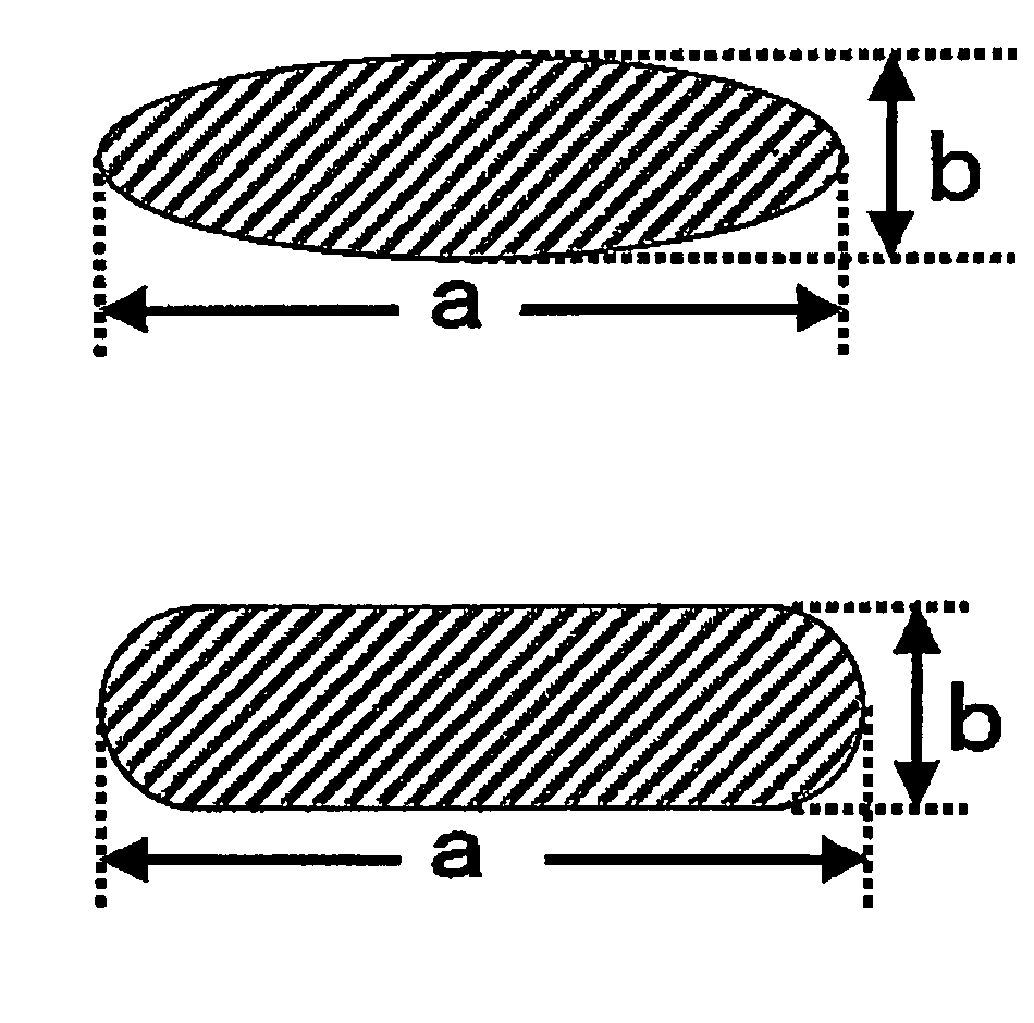
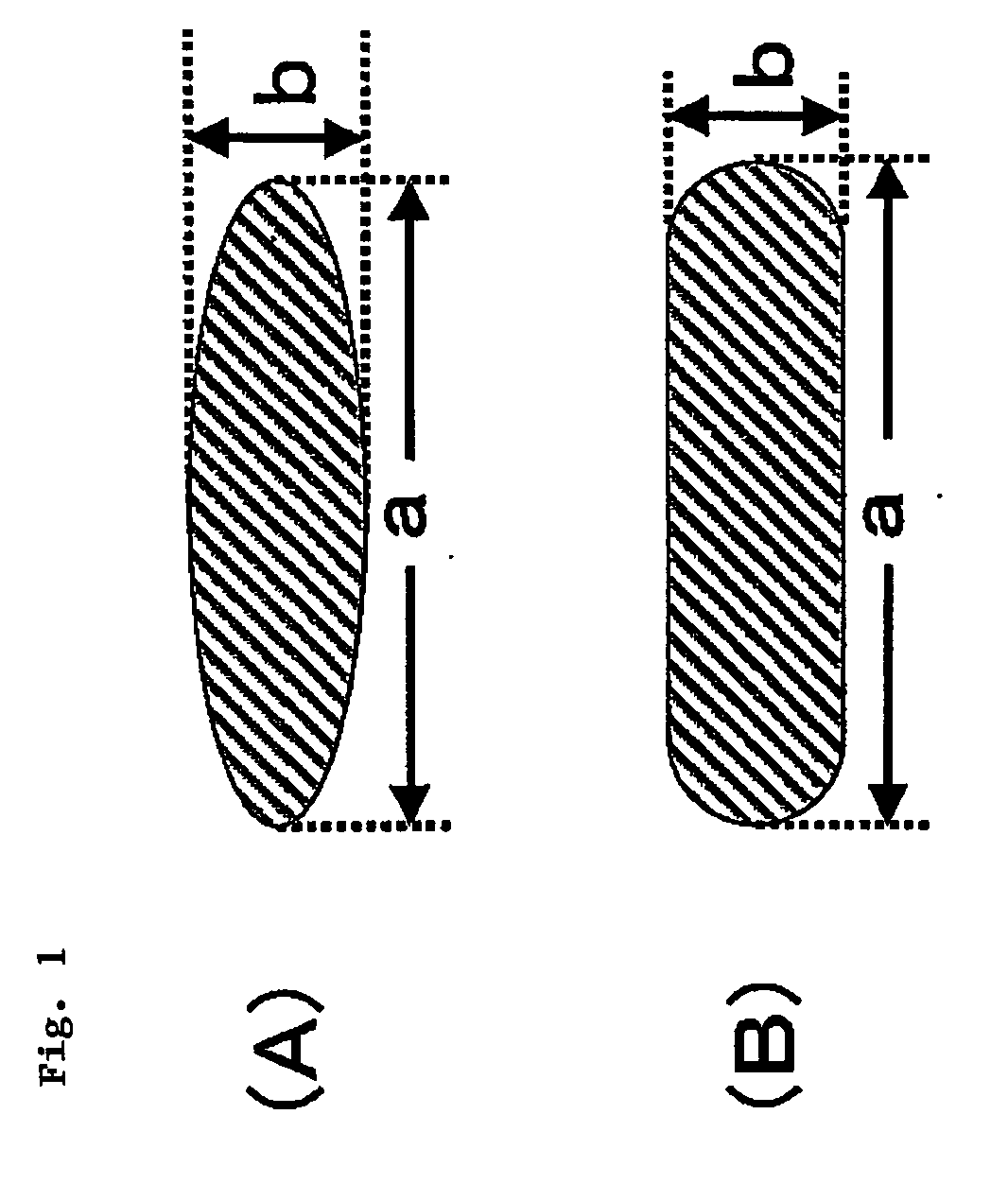
[0054] The filament cross-section profile of the yarn for the coated base fabric for airbags of the invention is generally oval as in FIG. 1(A), or corner-rounded rectangular oval as in FIG. 1(B). Apart from such oval profiles, it may be any others of which the major axis (a) and the minor axis (b) satisfy the relationship mentioned below. For example, it includes not only bilateral symmetric configurations such as rectangles, diamonds, cocoons, but also bilateral asymmetric configurations or their combinations. In addition, the basic configurations as above may be modified to have projections or recesses or to have hollows, not detracting from the effect of the invention.

Problems solved by technology

In addition, the technique is characterized by increasing the bulkiness of fabrics to thereby increase the thickness of the fabrics that are still flexible.
However, the base fabric is not coated, or that is, the technique is for attaining reduced air permeability of non-coated base fabrics, and is not for attaining improved compactness and containability of coated base fabrics that are formed by coating base fabrics with resin.
However, the technique disclosed is for improving the producibility of the fibers by forming the projections in the filament cross-section thereof, while, on the other hand, the projections interfere with the packing capability of the filaments, and, as a result, the fabric formed of the fibers is unsatisfactory in point of reducing the thickness thereof.
However, this is silent on a technique of making the best use of the characteristics of flattened yarns as much as possible, or that is, this gives no description of indicating a technique for aligning the constitutive fibers in a base fabric in such a manner that the major axis of the warp and the weft to constitute the base fabric is highly oriented in the horizontal direction of the base fabric in the cross-section thereof.
The polyester fiber fabrics formed of the diamond-shaped or S-shaped flattened cross-section yarns described in the patent specification surely have good covering capability and are highly flexible although they are formed of polyester fibers, but when compared with fabrics of polyamide fibers, it could not be said that the polyester fiber fabrics are specifically effective.
Non-coated airbags are surely advantageous over coated airbags in point of the compactness, containability and cost reduction, but are disadvantageous than the latter in point of the heat resistance and the gas imperviousness, and, in addition, the safety of the former would be problematic as compared with that of the latter.

Method used


Image

  • Base cloth for coated airbag and method for manufacturing the same
  • Base cloth for coated airbag and method for manufacturing the same
  • Base cloth for coated airbag and method for manufacturing the same

Examples


examples

[0099] The invention is described concretely with reference to the following Examples and Comparative Examples.

[0100] The physical properties referred to in the specification and in the following Examples are measured according to the methods mentioned below.

Properties of Yarns:

[Degree of Flatness]:

[0101] Fibers are cut, and their cross-sections are photographed through an optical microscope (×200). On the picture, the major axis length (a) and the minor axis length (b) of each fiber cross-section are measured, and its ratio indicates the degree of flatness of the fiber analyzed. 10 filaments are analyzed and their data are averaged.

Degree of Flatness=a / b.

[Total Fineness]:

[0102] According to the method of JIS L-1013, the conditioned weight fineness is determined.

[Filament Fineness]:

[0103] The total fineness is divided by the number of the filaments analyzed.

[Tenacity, Elongation]:

[0104] A sample to be analyzed is left as hanks in a temperature-humidity conditioned ro...

examples 1 to 8

, Comparative Examples 1 to 5

[0124] Using an extruder-type spinning machine, nylon 66 chips having a sulfuric acid-relative viscosity (measured in 98% sulfuric acid at 25° C.) of 3.7, and containing 70 ppm, in terms of copper, of copper acetate, 0.1% by weight of potassium iodide and 0.1% by weight of potassium bromide were melted, and the polymer melt was metered via a metering pump and then fed into a spinning pack. The polymer melt was filtered through the spinning pack, and then spun out via a spinneret. The temperature of the extruder and that of the spinning block (spinning beam) were so controlled that the spinning temperature (the polymer temperature at the spinning pack inlet) could be 295° C. The spinnerets were differently designed for flattened cross-section yarns and circular cross-section yarns in point of the total fineness, the number of filaments, the filament fineness and the degree of flatness of the yarns to be produced. Concretely, the number of orifices, the or...


PUM

PropertyMeasurementUnit
Temperatureaaaaaaaaaa
Lengthaaaaaaaaaa

Abstract

A coated base fabric for airbags, which is fabricated by applying a resin elastomer to a base fabric formed of flattened cross-section yarns having a degree of filament cross-section flatness (that is, a ratio of the major axis length to the minor axis length of the filament cross-section) of from 1.5 to 8, and which is characterized in that the filaments are aligned in the base fabric in such a manner that the total average horizontal index (HI) represented by the following formula falls within a range of from 0.75 to 1.0, and the amount of the resin elastomer adhered to the fabric is from 0.1 to 60 g / m2: HI=(Σhi) / f wherein hi=cos θ, θ indicates the angle between the major axis direction of each filament and the horizontal direction of the fabric, f indicates the number of the filaments.

Description

TECHNICAL FIELD [0001] The present invention relates to a base fabric for airbags, which is coated with a resin elastomer on its surface and which has good mechanical properties, heat resistance, compactness and containability, and relates to a method for manufacturing it. [0002] At present, airbags are indispensable for ensuring the safety of drivers and passengers in automobiles, and the percentage of airbag installation in automobiles is increasing. [0003] The requirement for improved reliability of airbags as safety devices is even more increasing, and the other requirements for compactness and cost reduction of airbag devices are also further more increasing. Accordingly, much more improvements are required for base fabrics for airbags and for the process of producing yarns and base fabrics for airbags so as to satisfy the above-mentioned requirements. [0004] Techniques have heretofore been disclosed for realizing air bags that are compactly foldable to save the necessary housi...

Claims


Application Information

Patent Timeline
IPC IPC(8): B60R21/16B60R21/235D01D5/253D01F6/60D03D1/02D06M15/693D06N3/00
CPCB60R21/235B60R2021/23514D06N3/0002D01F6/60D03D1/02D01D5/253Y10T442/2369Y10T442/3065Y10T442/3089Y10T442/3114B60R21/16D06M15/643
Inventor OKADA, TAIICHI
Owner TORAY IND INC
Learn More