
Self-diagnosing system for encoder

a self-diagnosing and encoder technology, applied in the field of encoders, can solve the problems of insufficient use of alarm information) transferred from the encoder to the control unit, difficulty in elucidating satisfactorily the cause of abnormal-state occurrence, etc., to achieve easy and accurate diagnosis, excellent maintenance characteristics and reliability

Active Publication Date: 2005-08-04
FANUC LTD
View PDF13 Cites 15 Cited by
  • Summary
  • Abstract
  • Description
  • Claims
  • Application Information

AI Technical Summary

Benefits of technology

[0009] It is an object of the present invention to provide a self-diagnosing system for an encoder, for detecting, by self-diagnosis, the occurrence of an abnormal state during the operation of an electric motor, which has both excellent maintenance characteristics and reliability, and in which it is possible to output information indicating the abnormal state to an external control unit, to confirm the operation state of the electric motor or the encoder at the instant of occurrence of the abnormal state at a desired timing after outputting the information, and thereby to easily and accurately specify the cause of the abnormal-state occurrence.

Problems solved by technology

In this configuration, a malfunction or abnormal state often occurs in the encoder itself or the electric motor due to various internal or external factors.
However, the data (i.e., the alarm information) transferred from the encoder to the control unit is often insufficient to be used to elucidate the cause of the abnormal state occurring in the encoder or the electric motor, because of a limit in the data transferring capacity.
Therefore, it is generally difficult to elucidate satisfactorily the cause of the abnormal-state occurrence, by using only the alarm information displayed or stored in the control unit.
In this case, the elucidation or the cause of the abnormal-state occurrence becomes more difficult.
However, the storage section does not store internal information on the encoder (i.e., data indicating an abnormal state) at the instant a malfunction or abnormal state occurs in the encoder or the servomotor.

Method used


Image

  • Self-diagnosing system for encoder
  • Self-diagnosing system for encoder
  • Self-diagnosing system for encoder

Examples


Embodiment Construction

[0023] The embodiments of the present invention are described below in detail, with reference to the accompanying drawings. In the drawings, the same or similar components are denoted by common reference numerals.

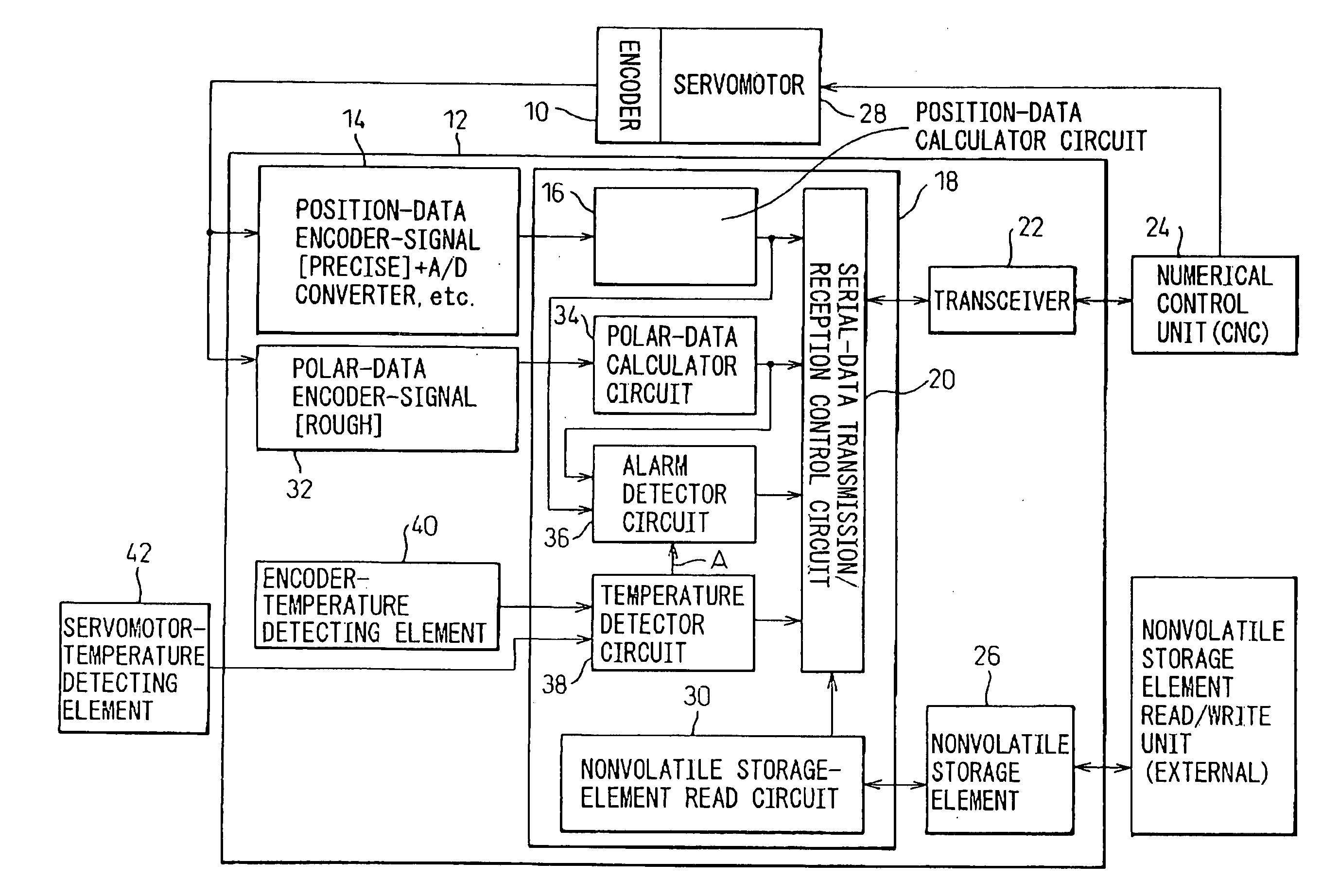
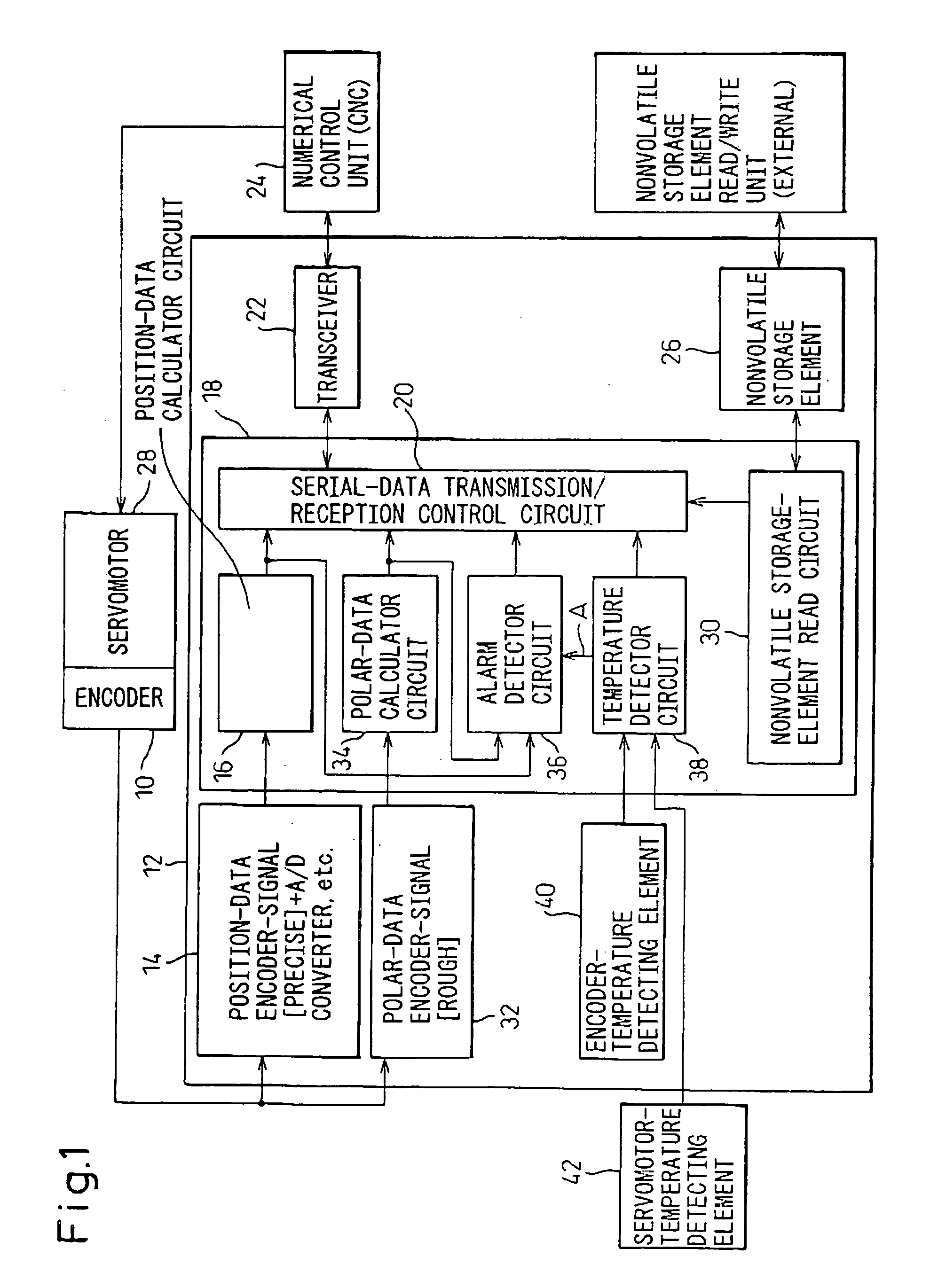
[0024] First, a self-diagnosing system for an encoder, as a related art of the present invention, is described with reference to FIG. 1. As illustrated, in this self-diagnosing system, an encoder circuit 12 for outputting information detected by an encoder 10 is provided with an encoder-signal amplifier circuit for position-data 14 incorporating therein an analog-to-digital (A / D) converter or the like, and a position-data calculator circuit 16 connected to the encoder-signal amplifier circuit for position-data 14. The encoder-signal amplifier circuit for position-data 14 is an analog signal circuit for amplifying signals of various phases (A-phase, B-phase, Z-phase, etc.), which are generated when an optical code plate (not shown) of the encoder 10 performs a rotation (in ...


PUM


Abstract

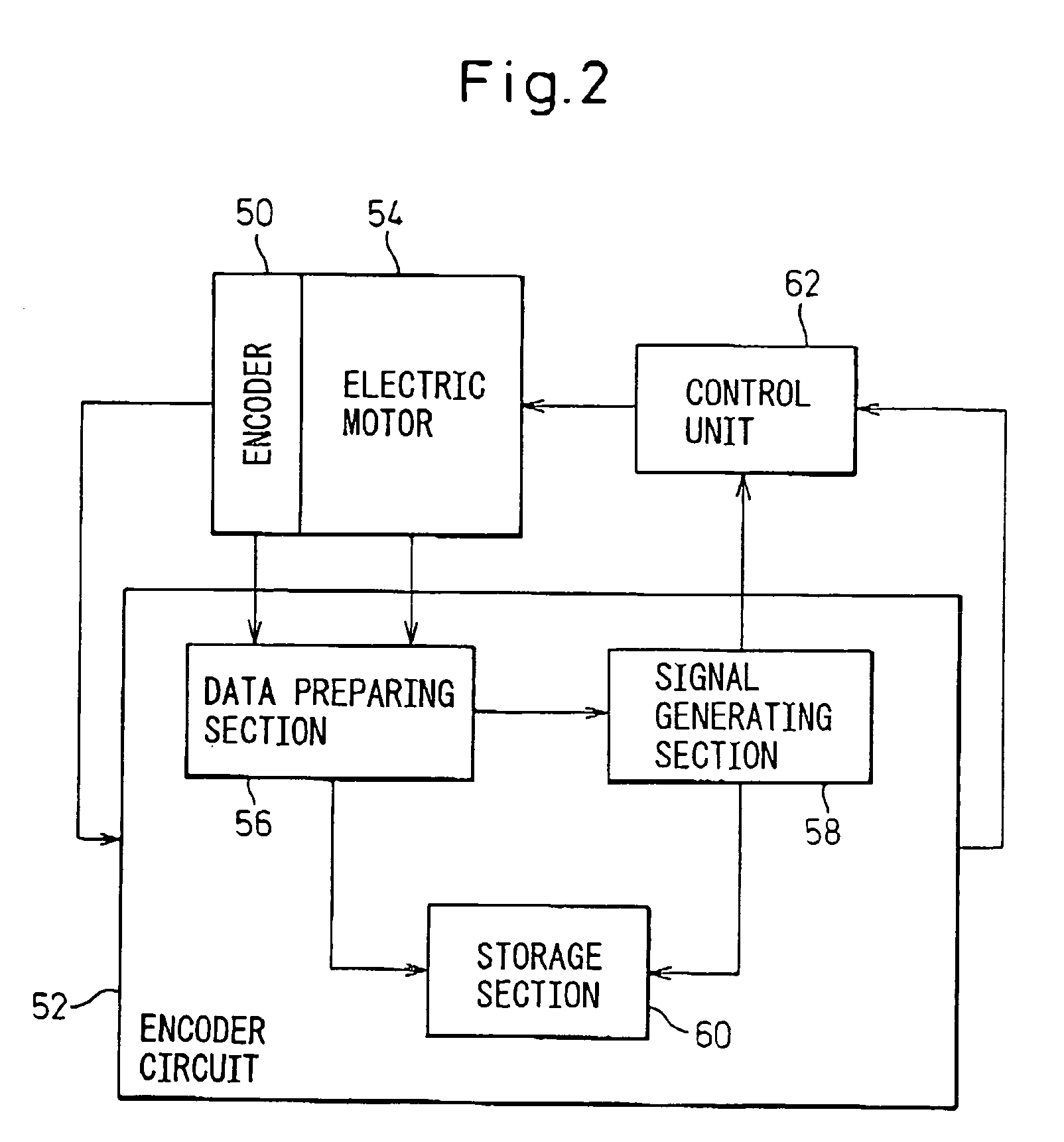
A self-diagnosing system for an encoder. The system includes an encoder circuit for outputting information detected by an encoder; a data preparing section provided in the encoder circuit and preparing data representing a state of an abnormal-state judgment factor in connection with at least one of the encoder and an electric motor combined with the encoder; a signal generating section provided in the encoder circuit and generating an abnormal-state signal when the data prepared in the data preparing section represents an abnormal state of the abnormal-state judgment factor; and a storage section provided in the encoder circuit and storing the data representing a state of the abnormal-state judgment factor when the signal generating section generates the abnormal-state signal. The storage section may store the data prepared in the data preparing section at a desired timing not later than the instant the signal generating section generates the abnormal-state signal.

Description

BACKGROUND OF THE INVENTION [0001] 1. Field of the Invention [0002] The present invention relates to an encoder for detecting the position and / or speed of an electric motor and, more particularly, to a self-diagnosing system for an encoder, which detects by a self-diagnosis the occurrence of a malfunction or abnormal state during operation of the electric motor. [0003] 2. Description of the Related Art [0004] As is generally known, an encoder is widely used to detect, e.g., the position and / or speed of a servomotor that drives an axis (i.e., a control axis) of a machine tool or an industrial robot. In this configuration, a malfunction or abnormal state often occurs in the encoder itself or the electric motor due to various internal or external factors. Therefore, it has been conducted that the encoder performs a self-diagnosis on whether a malfunction or abnormal state has occurred in connection with a predetermined check item, and that, when the result of the self-diagnosis is obta...

Claims


Application Information

Patent Timeline
IPC IPC(8): G01D5/245G01D5/244
CPCG01D5/24461G01D5/24457
Inventor TANIGUCHI, MITSUYUKIKIKUCHI, HIROFUMIMIYAMOTO, HAJIME
Owner FANUC LTD
Learn More