Wear plate assembly

a technology of wear plate and assembly, which is applied in the direction of mechanical machines/dredgers, soil shifting machines/dredgers, constructions, etc., can solve the problems of reducing the wear so as to reduce or eliminate the movement of the wear plate, reduce the shear stress of the bolt, and the effect of thickening the wear lip section

Inactive Publication Date: 2005-08-11
PENINSULA ALLOY +1
View PDF7 Cites 53 Cited by
  • Summary
  • Abstract
  • Description
  • Claims
  • Application Information

AI Technical Summary

Benefits of technology

[0018] In another aspect or feature of the invention, there is a single flange, bolted lip-to-base-plate connection that may tend to reduce or eliminate lip movement relative to the base plate during operation. This may tend to reduce bolt shear stresses as compared to the dual flange arrangement mentioned above. In a further aspect or feature of the invention, the base plate has a sloped or chamfered section that extends rearwardly and downwardly from the flat abutment of the forward edge the base plate to its base-side, or surface. This chamfer may tend to permit a thicker wear lip section in the critical area.
[0019] In another aspect or feature of the invention, the wear segments have a wedge shape that may tend to promote relatively even top and bottom wear and may tend to reduce friction when penetrating a pile of loose material. The wedge shape may tend to present a reduced impediment to material flowing into, or out of, the bucket due to a thinner top section flange at the base plate connection. In a further feature of that aspect of the invention, the lip has a

Problems solved by technology

During operation, these buckets tend to wear along their leading edges due to abrasion when entering the material pile and during contact with the ground.
During use, the lip may tend to wear down, sometimes very quickly.
Time may be lost if the loader is transported to a shop where the bucket can be replaced.
If a replacement bucket is not available or the replacement process is too cumbersome at the time, an operator may continue operating the loader nonetheless.
As a result the base plate or the bucket itself may be damaged through overuse and may then require much more extensive repair than would otherwise be expected.
The replacement of the base plate or bucket may well be much more costly than the use gained by operating the loader for the extra time.
Releasable mechanical fastener systems, by contrast, tend to be regarded with considerable scepticism in view of the high stresses in the lip area during operation.
However, mechanical fastening, as opposed to welding, permits different casting alloys to be used for the wear segments, and may tend to reduce reliance on specific welding skills to produce good welds in high wear alloys, such as, for examp

Method used


Image

  • Wear plate assembly
  • Wear plate assembly
  • Wear plate assembly

Examples


Embodiment Construction

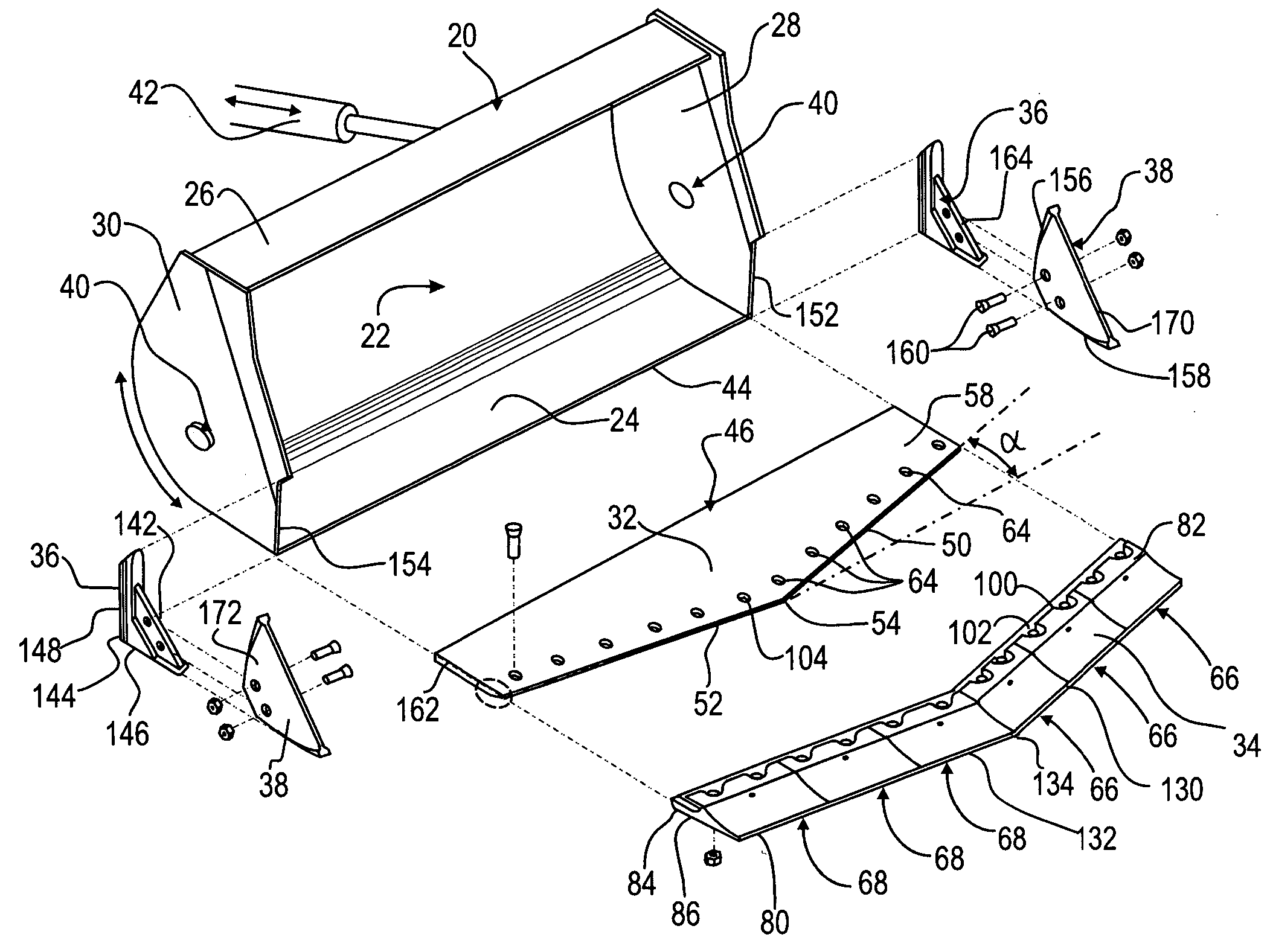
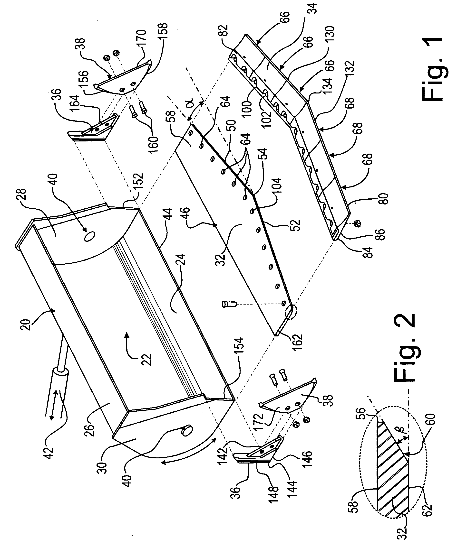
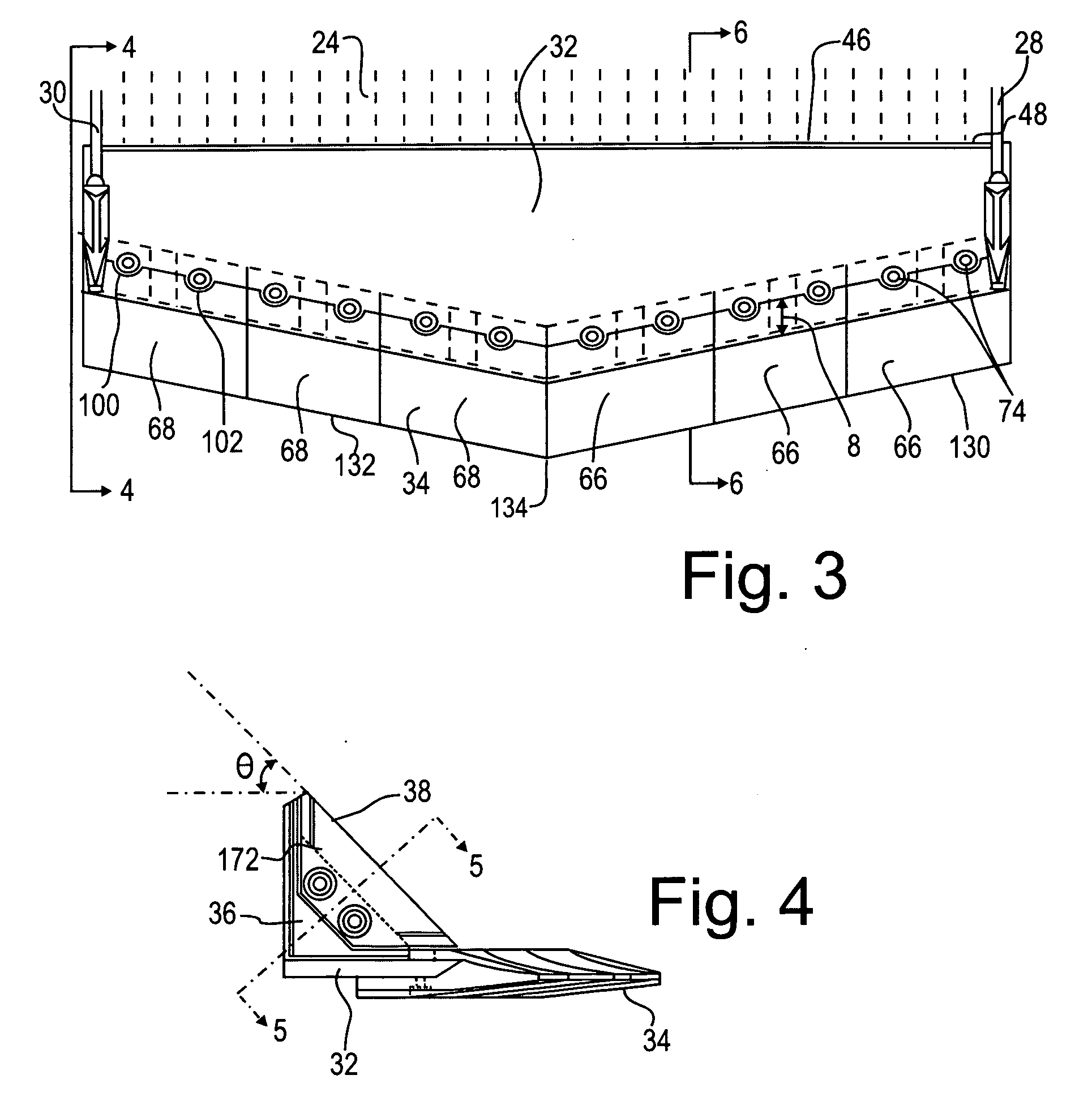
[0060] The description that follows, and the embodiments described therein, are provided by way of examples of particular embodiments of the principles of the present invention. These examples are provided for the purposes of illustration, and not of limitation, of those principles and of the invention. In the description that follows, like parts are marked throughout the specification and drawings with the same respective reference numerals. The drawings are not necessarily to scale and in some instances proportions may have been exaggerated in order more clearly to depict certain features of the invention. In this description the terms “leading” or “forward” refer to the direction of advance of the equipment into a work substance, be it earth, or gravel, or rock, or some other substance.

[0061] By way of general overview, FIG. 1 shows an exploded view of a bucket 20 of a front end loader (not shown) having wear components for installation thereon. Bucket 20 has a backshell assembl...


PUM


Abstract

A bucket assembly is provided with a kit that includes a base plate for permanent connection to a lower part of the bucket, and sacrificial, impermanent replaceable wear edge segments for the forward lip and corner leading edges of an excavator or loader bucket. These segments form a set of “bolt on” cast wear members and wing wear segments. The base plate and wear plates are drilled and machined to accommodate the precision fitting bolting on of the replaceable lips and cast wing segments. The cast lip segments are of both left and right hand configurations and come in a variety of widths that, in combination, may tend to fit a large number of different commercially available bucket sizes. The lip top and bottom faces are shaped in a profile that may tend to result in relatively uniform wear and a reduction in friction when digging into various materials.

Description

RELATED APPLICATIONS [0001] This is a continuation-in-part of application Ser. No. 09 / 971,540 filed on Oct. 09, 2001, now abandoned.FIELD OF THE INVENTION [0002] This invention relates to the field of wear plate assemblies for loader buckets. BACKGROUND OF THE INVENTION [0003] In the mining and construction industries, loading and moving of heavy materials such as sand, gravel and rock is often accomplished using heavy machinery such as scoop trams, front-end loaders and powered bucket digging devices. During operation, these buckets tend to wear along their leading edges due to abrasion when entering the material pile and during contact with the ground. During use, the lip may tend to wear down, sometimes very quickly. After the lip wears down to a point where the base plate or bucket are threatened with wear, the bucket may typically be removed and sent to be refurbished by replacing the lip. Bucket removal is a relatively common practice in the mining industry at present. Rework ...

Claims


Application Information

Patent Timeline
IPC IPC(8): E02F3/36E02F3/815E02F9/28
CPCE02F3/40E02F9/2883E02F9/28E02F3/8152
Inventor GRANT, JAMES
Owner PENINSULA ALLOY
Why Eureka
Try Eureka