
Diagnostic and control methods for internally calibrated oxygen sensor

a technology of oxygen sensor and internal calibration, which is applied in the direction of liquid/fluent solid measurement, material electrochemical variables, instruments, etc., can solve the problems of sensor and sensor being considered to have fine physical leakage, and sensor being considered to have gross physical leakag

Active Publication Date: 2005-08-11
BAKER HUGHES INC
View PDF1 Cites 14 Cited by
  • Summary
  • Abstract
  • Description
  • Claims
  • Application Information

AI Technical Summary

Benefits of technology

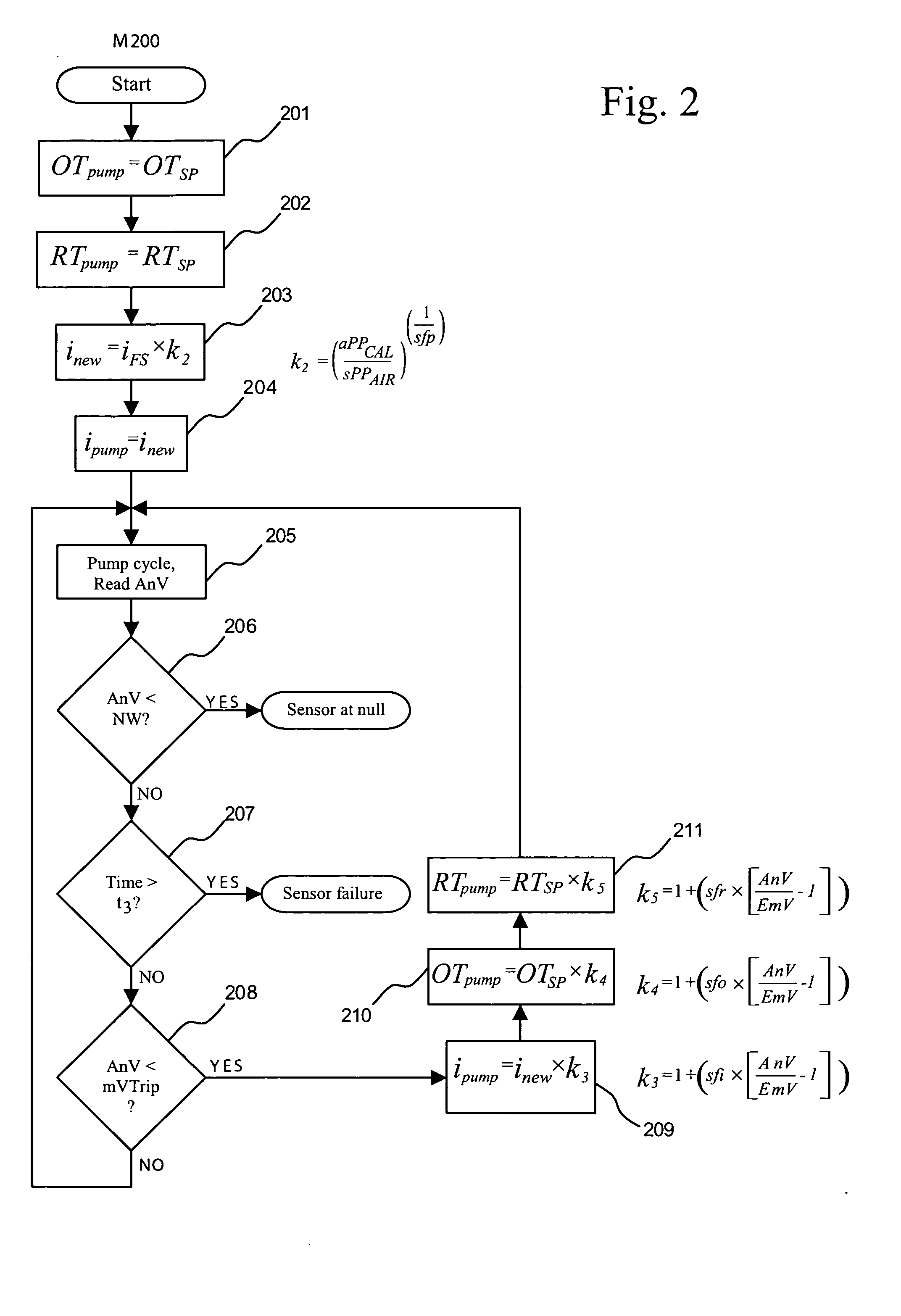
[0012] In a further aspect of the first embodiment, the initial value of the pumping current pulse magnitude presented to a calibration factor generation process is reduced as a function of the relationship between the oxygen partial pressure of air at a standardized atmospheric pressure and the oxygen partial pressure of a calibration gas against which the sensor is calibrated. The effect of this reduction is to scale down the pumping current in relation to the calibration gas oxygen partial pressure thereby avoiding the potential problem of over pumping the sensor at low oxygen partial pressures.
[0014] In a further aspect of the first embodiment, the instantaneous values of the pumping current pulse magnitude, pumping current pulse application time and post pumping current pulse relaxation time are dynamically reduced as a function of the instantaneous measured Nernst voltage as the sensor approaches the null or balance point during a calibration or initialization process or during an internal reference tracking process. The effect of this dynamic manipulation is to avoid the potential problem of oscillatory behavior close to the pumped sensor null or balance point.

Problems solved by technology

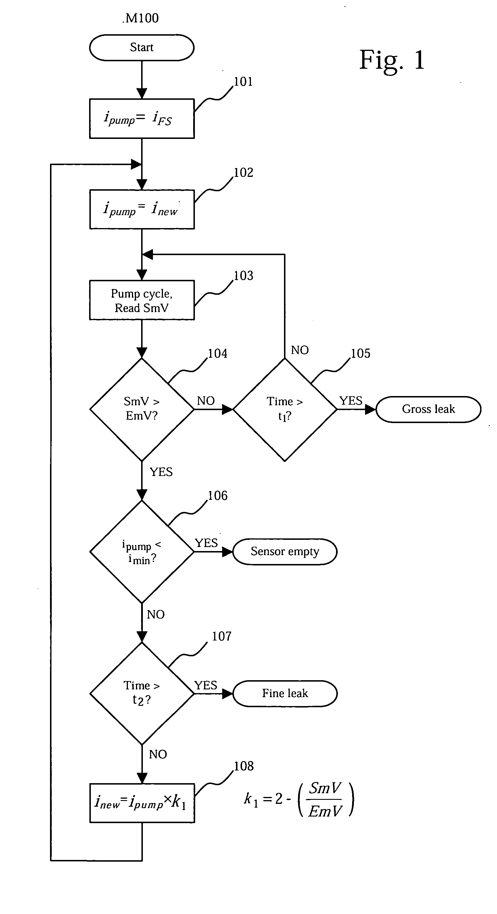
If the sensor fails to achieve an empty state as defined by a specific, programmed output voltage target value, within the specified time limit, the sensor is considered to have a gross physical leak.
If the sensor fails to achieve the predetermined low limit pumping current value within the specified time limit value, the sensor is considered to have a fine physical leak.

Method used


Image

  • Diagnostic and control methods for internally calibrated oxygen sensor
  • Diagnostic and control methods for internally calibrated oxygen sensor
  • Diagnostic and control methods for internally calibrated oxygen sensor

Examples


Embodiment Construction

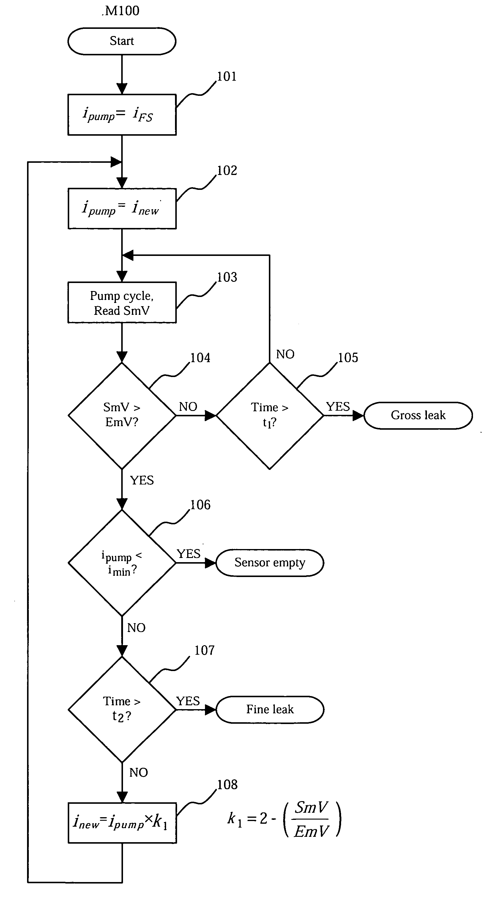
[0021]FIG. 1 shows a method for performing a simultaneous physical leak check and emptying of a sensor sealed reference chamber. In step 101 an intermediate calculation variable inew, is set to a first maximum value iFS, representing a fixed upper limit to the current available to pump the sensor internal reference chamber. More specifically, this value may represent the maximum design limit of a particular hardware circuit used to effect sensor pumping actions.

[0022] In step 102 ipump, the pump circuit magnitude control variable is initialized to the starting upper limit value inew. The value stored in ipump is passed to the control circuit 20 (FIG. 5) to effect the emptying of the internal reference chamber. Steps 103 through 105 comprise the internal reference chamber pump-out sub-loop, ELoop. Step 103 activates the sensor pumping mechanism within the control circuit 20 and queries the developing sensor output voltage. The DC current value ipump is latched into the control circu...


PUM


Abstract

A set of methods controls the pumping action of and provides leak checking of a solid electrolyte oxygen sensor having internal and external electrodes. A first method performs a leak check on the sensor by forcing the sensor internal reference chamber to an evacuated state while seeking a minimum pumping current able to maintain this state. Further pumping control methods apply current pulses to the sensor electrodes to achieve a balanced state between an external oxygen partial pressure and an internal reference oxygen partial pressure. Reduction expressions modify the pulse parameters as a function of the sensor voltage output. A further expression modifies the pulse magnitude as a function of the internal reference chamber oxygen partial pressure. A further expression modifies the initial value of the pulse magnitude as a function of the oxygen partial pressure in a calibration gas during a calibration process.

Description

BACKGROUND OF THE INVENTION [0001] The present invention relates, in general, to the control of solid electrolyte sensors used to detect the level of oxygen in a gaseous environment and, in particular, to the control of oxygen sensors, containing a pump-able sealed internal reference chamber. [0002] A conventional solid electrolyte oxygen sensor is described in U.S. Pat. No. 6,177,001 ('001 Patent). FIGS. 5 and 6 show a conventional sensor 2 formed of a solid oxide material, typically zirconia that includes a tubular shell 4 that is closed at one end. The shell forms a cylindrical chamber 6 that is sealed, for example, by having a plug 8 at the open end of the tube shell. The outside surface 10 of the oxide tubular shell is coated with porous platinum to create an outer electrode exposed to gases external to the sensor, such as in a heated environment 14. The cylindrical inside surface 12 of the oxide shell is coated with porous platinum to create an inner electrode exposed to the g...

Claims


Application Information

Patent Timeline
IPC IPC(8): G01N27/407G01N27/417
CPCG01N27/4175
Inventor BOWDEN, MARK EDWARD
Owner BAKER HUGHES INC
Learn More