Pressure balanced fluid control device

Active Publication Date: 2005-08-11
FMC TECH INC
View PDF3 Cites 30 Cited by
  • Summary
  • Abstract
  • Description
  • Claims
  • Application Information

AI Technical Summary

Benefits of technology

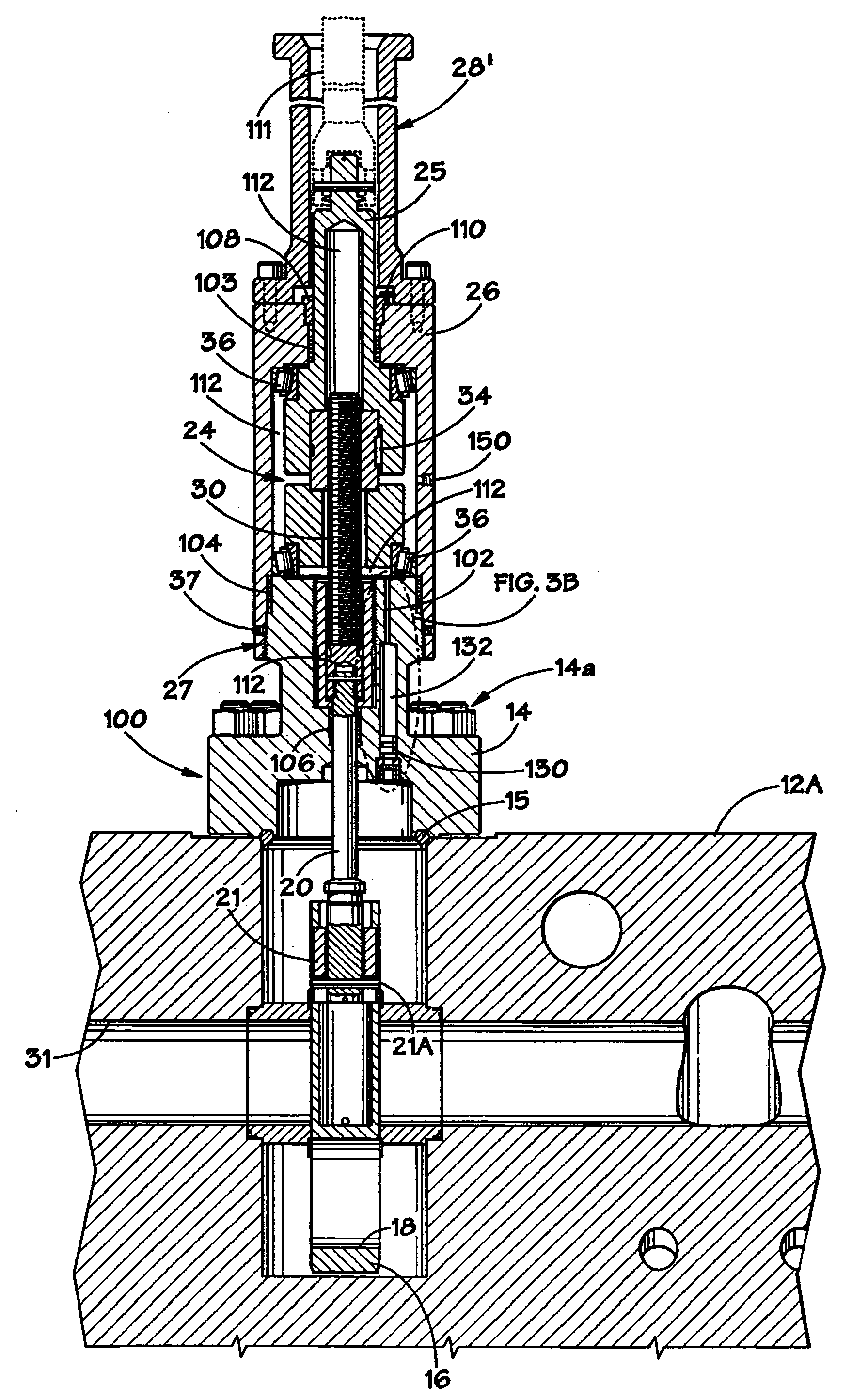
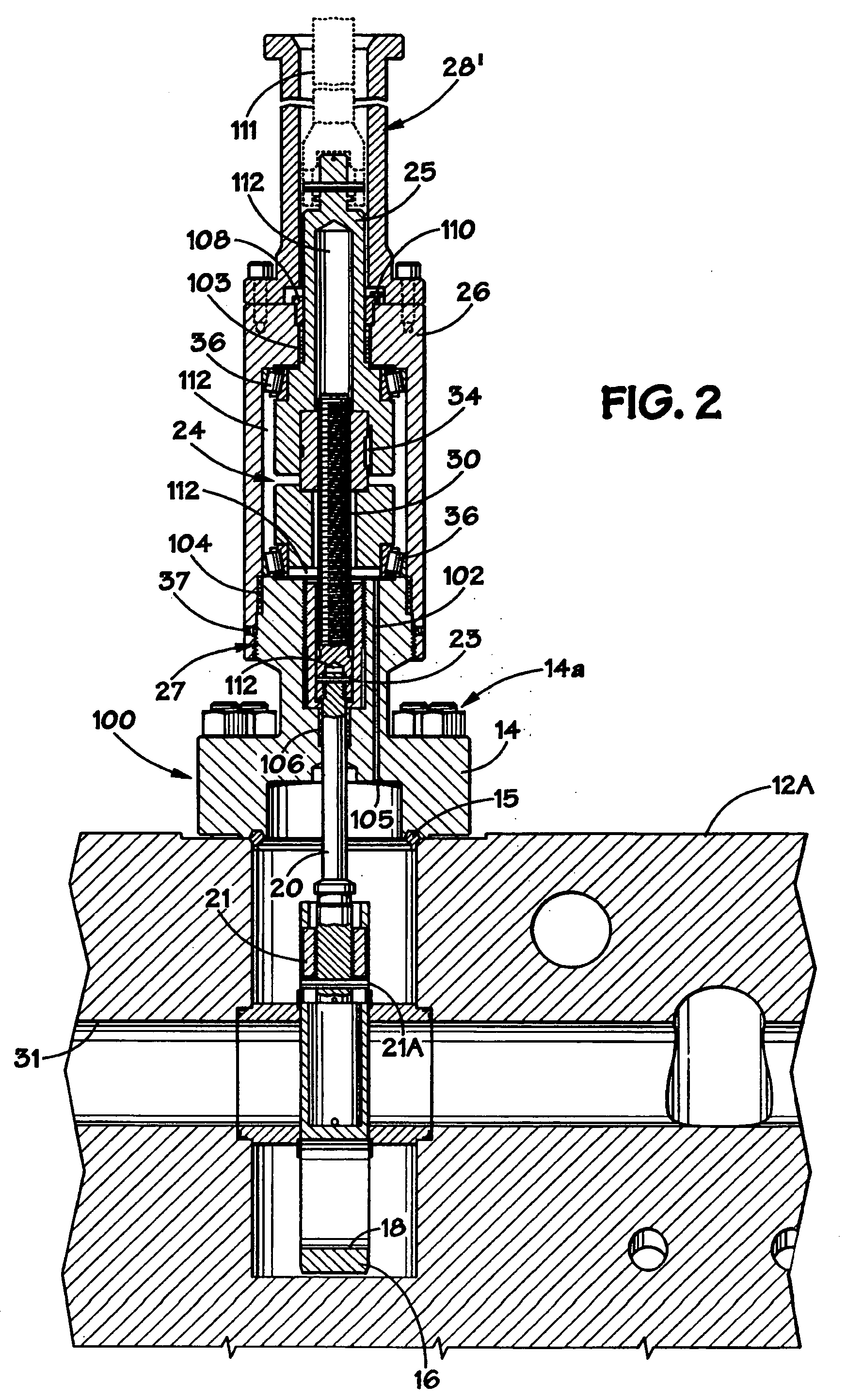
[0020] In still a further illustrative embodiment, the device comprises a body, a bonnet coupled to the body, a valve stem operatively coupled to a gate positioned in the body, a valve stem seal positioned between the valve stem and the bonne

Problems solved by technology

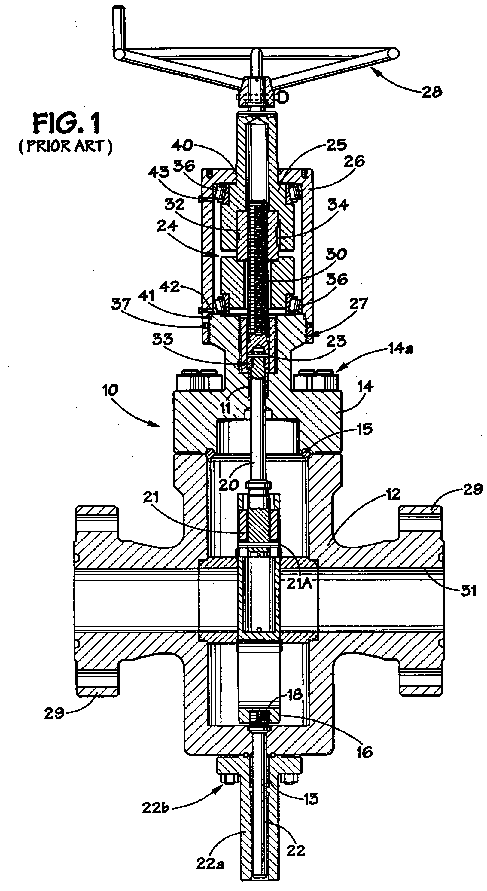
As is well known in the art, in an unbalanced stem gate valve, there is a net force exerted on the valve stem.
In unbalanced gate valve designs, it is often necessary to limit the stem seal area to reduce the unbalanced stem force and thus the operating torque required to actuate the gate valve.
Although reducing the stem seal area may reduce unbalanced forces, such a limitation may place a number of undesirable constraints on the design of a gate valve.
One drawback to the use of such a balanced stem design is that the second stem increases the size, cost and complexity of the valve, and introduces additional potential leak paths.
For example, in many subsea applications, there is no available space for incorporating a balance stem into the design of the subsea equipment, e.g., a Christmas tree.
However, such high torque actuation systems present several problems.
For example, with respect to manual

Method used


Image

  • Pressure balanced fluid control device
  • Pressure balanced fluid control device
  • Pressure balanced fluid control device

Examples


Embodiment Construction

[0026] Illustrative embodiments of the invention are described below. In the interest of clarity, not all features of an actual implementation are described in this specification. It will of course be appreciated that in the development of any such actual embodiment, numerous implementation-specific decisions must be made to achieve the developers' specific goals, such as compliance with system-related and business-related constraints, which will vary from one implementation to another. Moreover, it will be appreciated that such a development effort might be complex and time-consuming, but would nevertheless be a routine undertaking for those of ordinary skill in the art having the benefit of this disclosure.

[0027] The present invention will now be described with reference to the attached figures. The words and phrases used herein should be understood and interpreted to have a meaning consistent with the understanding of those words and phrases by those skilled in the relevant art....


PUM


Abstract

The present invention is directed to a pressure balanced fluid control device. In one illustrative embodiment, the device comprises a body, a bonnet coupled to the body, a valve stem operatively coupled to a gate positioned in the body, a valve stem seal positioned between the valve stem and the bonnet, wherein a sealed cavity exists above the valve stem seal, and an opening through the bonnet that is adapted to allow a pressure of a working fluid flowing through the valve to be exerted in the sealed cavity above the valve stem seal. In another illustrative embodiment, the device comprises a body, a bonnet coupled to the body, a valve stem operatively coupled to a gate positioned in the body, a valve stem seal positioned between the valve stem and the bonnet, wherein a sealed cavity exists above the valve stem seal, and an opening through the bonnet, the opening being in fluid communication with the sealed cavity and an interior region of the body. In a further illustrative embodiment, the device comprises a body, a bonnet coupled to the body, a valve stem operatively coupled to a gate positioned in the body, a valve stem seal positioned between the valve stem and the bonnet, wherein a sealed cavity exists above the valve stem seal, a piston chamber formed in the bonnet, the piston chamber being in fluid communication with the sealed cavity and an interior region of the body, and a piston positioned in the piston chamber.

Description

BACKGROUND OF THE INVENTION [0001] 1. Field of the Invention [0002] The present invention is generally related to the field of pressure control devices, and, in one particular example, to a pressure balanced fluid control device. [0003] 2. Description of the Related Art [0004] Fluid control devices, such as gate valves, are commonly employed in a variety of different industries, e.g., surface and subsea oil and gas drilling and producing industries. Gate valves may be classified as either balanced stem or unbalanced stem valves. As is well known in the art, in an unbalanced stem gate valve, there is a net force exerted on the valve stem. In some cases, this force may be equal to the pressure exerted within the valve body multiplied by the seal area of the stem. In unbalanced gate valve designs, it is often necessary to limit the stem seal area to reduce the unbalanced stem force and thus the operating torque required to actuate the gate valve. Although reducing the stem seal area ma...

Claims


Application Information

Patent Timeline
IPC IPC(8): F16K3/02F16K31/50
CPCF16K31/508F16K3/0254F16K3/30F16K39/04
Inventor ZHENG, QIU SHI
Owner FMC TECH INC
Why Eureka
Try Eureka