
Device for generating a pair of true/complement-phase logic signals

a logic signal and logic technology, applied in the direction of oscillator generators, pulse techniques, multiple input and output pulse circuits, etc., can solve the problems of reducing the rate of data transmission, significant noise generation, and limited length of cables, so as to achieve precise differential signals and reduce the bit error rate at the receiver end

Inactive Publication Date: 2005-08-11
ITE TECH INC
View PDF4 Cites 16 Cited by
  • Summary
  • Abstract
  • Description
  • Claims
  • Application Information

AI Technical Summary

Benefits of technology

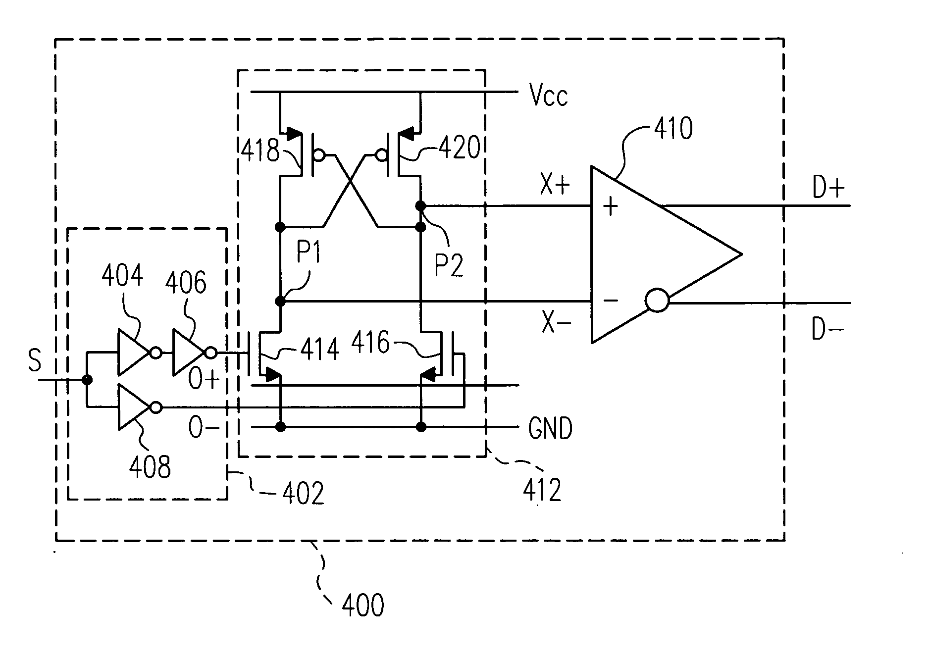
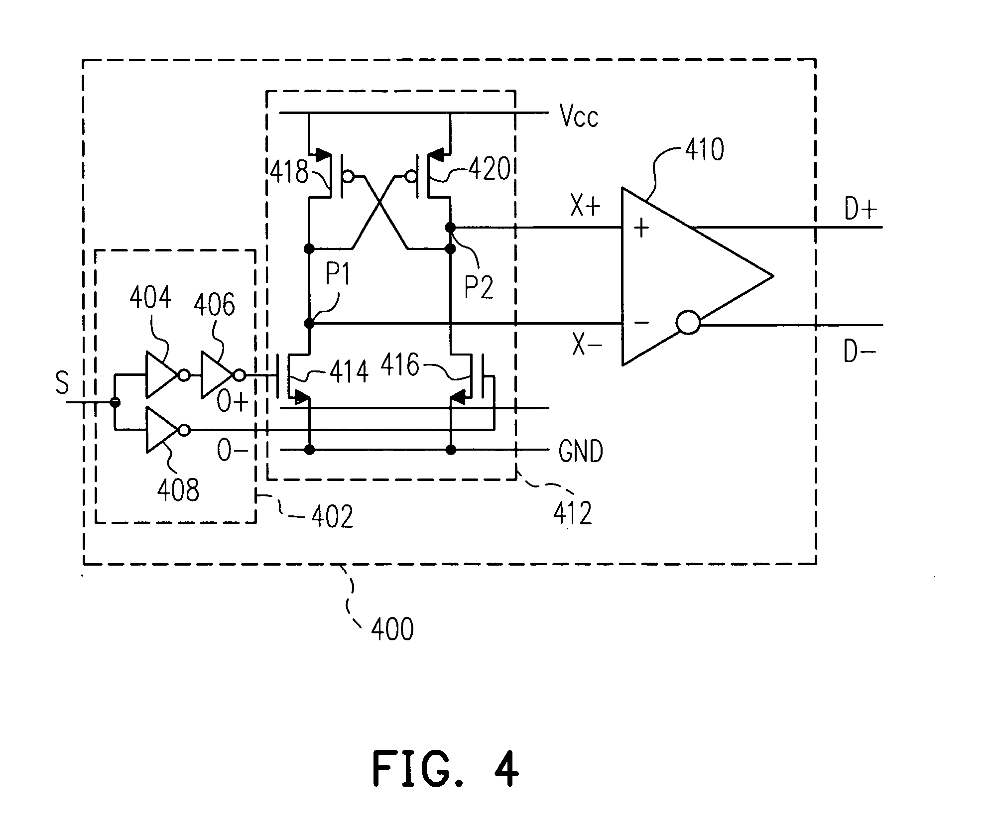
The present invention provides a device and method for generating a pair of true / complementary-phase logic signals that can reduce the impact of process and operation condition variations, and minimize bit error rates at the receiver end. The device includes a single-end to true / complementary-phase signal conversion circuit, a first stage circuit, a second stage circuit, and a differential amplifier. The first stage circuit converts a single-end signal to a first pair of true / complementary-phase signals, while the second stage circuit performs a feedback control to obtain a second pair of true / complementary-phase signals. The differential amplifier then outputs a pair of differential signals with synchronized rising and falling times. The invention can provide a long-distance, low-bit error rate data transmission.

Problems solved by technology

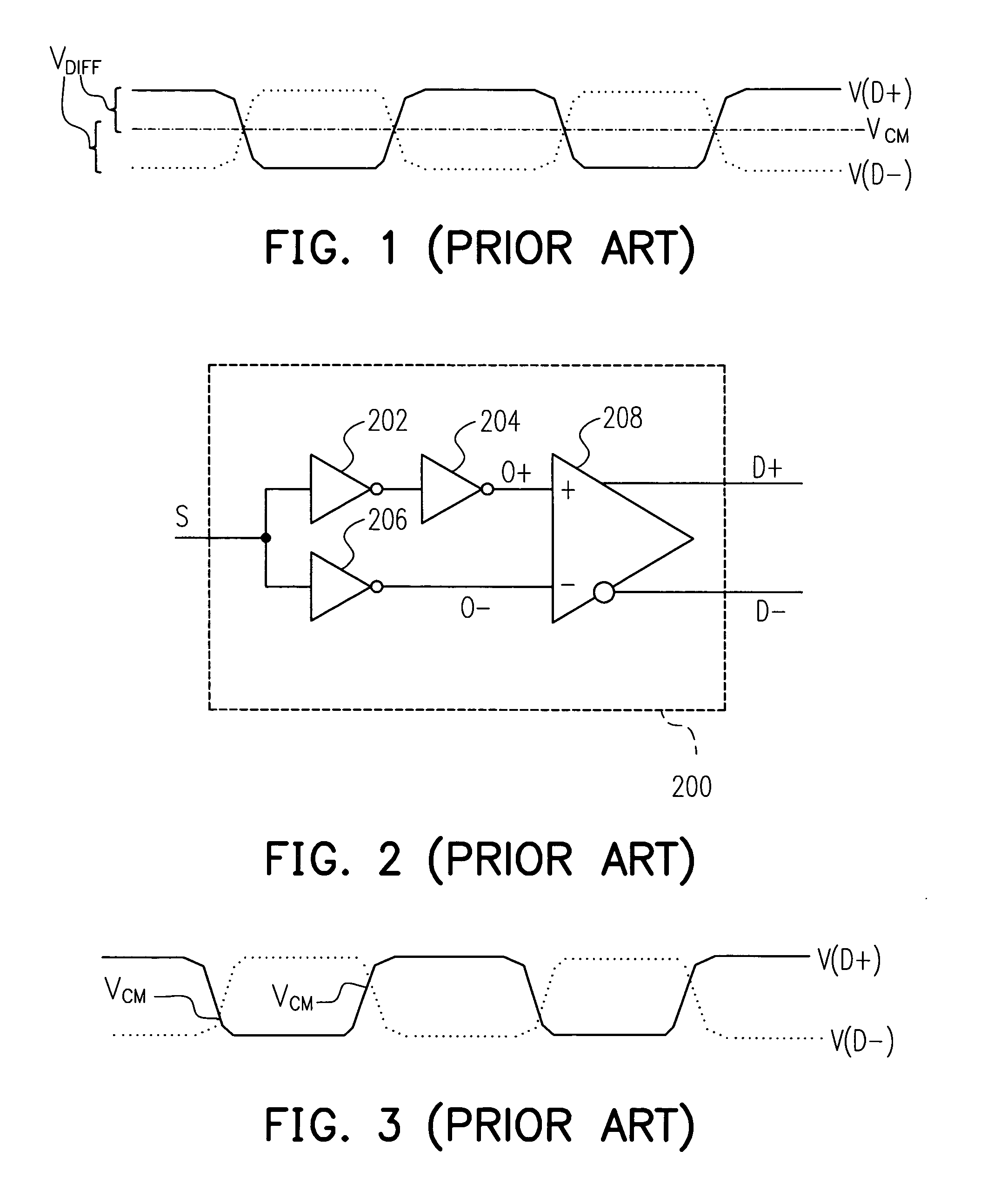
Hence, when all the voltage levels of the bits of the data signal are changed at the same time, a significant noise is generated.
The noise may reduce the rate of data transmission drastically.
In addition, the length of the cables is limited due to the decay of the data signals during the signal transmission.

Method used


Image

  • Device for generating a pair of true/complement-phase logic signals
  • Device for generating a pair of true/complement-phase logic signals
  • Device for generating a pair of true/complement-phase logic signals

Examples


Embodiment Construction

[0026] The present invention now will be described more fully hereinafter with reference to the accompanying drawings, in which preferred embodiments of the invention are shown. This invention may, however, be embodied in many different forms and should not be construed as limited to the embodiments set forth herein; rather, these embodiments are provided so that this disclosure will be thorough and complete, and will fully convey the scope of the invention to those skilled in the art. Like numbers refer to like elements throughout.

[0027]FIG. 4 is a circuit diagram of a device for generating a pair of T / C-phase logic signals in accordance with an embodiment of the present invention. Referring to FIG. 4, the device for generating a pair of T / C-phase logic signals 400 includes, for example but not limited to, a single-end to T / C-phase signal circuit 402, a differential amplifier 410, and a first stage circuit 412. The single-end to T / C-phase signal circuit 402 includes, for example b...


PUM


Abstract

A device for generating a pair of true / complementary-phase logic signals is provided. The device comprises a single-end to true / complementary-phase signal conversion circuit, a first stage circuit and a differential amplifier. The conversion circuit receives a single-end signal and converting the single-end signal to a first pair of true / complementary-phase signals. The first stage circuit receives the first pair of true / complementary-phase signals and performing a feedback control to obtain a second pair of true / complementary-phase signals. The differential amplifier receives the second pair of true / complementary-phase signals and outputs a pair of differential signals. Therefore, the rising time / falling time of one of the pair of differential signals is synchronized with the falling time / rising time of the other of the pair of differential signals.

Description

CROSS-REFERENCE TO RELATED APPLICATION [0001] This application claims the priority benefit of Taiwan application serial no. 93102572, filed on Feb. 5, 2004. BACKGROUND OF THE INVENTION [0002] 1. Field of the Invention [0003] The invention generally relates to a device for generating a pair of true / complement-phase (T / C-phase) logic signals. More particularly, the present invention relates to a device for generating a pair of true / complement-phase (T / C-phase) logic signals with feedback control. [0004] 2. Description of Related Art [0005] In recent years, since the processing speed of computer has been significantly enhanced, the data transmission interface and data processing method have to be developed to meet the requirement of the computer. Traditionally, when using the transistor-transistor logic (TTL) signal level for parallel transmission of data, cables with number of wires same as the number of bits of the bandwidth of the data signal are required. Hence, when all the voltag...

Claims


Application Information

Patent Timeline
Patent Type & Authority Applications(United States)
IPC IPC(8): H03K3/00H03K3/356H03K5/151H03K5/22
CPCH03K5/151H03K3/356113
Inventor HU, TING-LI
Owner ITE TECH INC
Learn More