Apparatus and Method for Transmission

a transmission method and apparatus technology, applied in the field of communication apparatus, can solve the problems of w-chip length exceeding the sum of propagation delay and delay variance of rach signal, and the apparatus has a greater propagation delay, so as to improve the probability of random access communication. the effect of success

Inactive Publication Date: 2005-08-11
PANASONIC CORP
View PDF9 Cites 19 Cited by
  • Summary
  • Abstract
  • Description
  • Claims
  • Application Information

AI Technical Summary

Benefits of technology

[0032] It is an object of the present invention to provide a transmission apparatus capable of improving the probability of successful random access communications without affecting the number of communication terminal apparatuses that can be accommodated and transmission capacity.
[0033] First, in view that the condition of a propagation path differs from one communication terminal apparatus to another and that a propagation delay of a communication terminal apparatus that has sent an RACH signal via a propagation path with a small propagation loss is small, while a propagation delay of a communication terminal apparatus that has sent an RACH signal via a propagation path with a large propagation loss is large, the present inventor et al. has come up with the present invention by discovering that assigning a known reference signal which will reduce the length of a delay profile that can be created to a communication terminal apparatus with a small propagation loss and assigning a known reference signal which will increase the length of a delay profile that can be created to a communication terminal apparatus with a large propagation loss will increase the probability that the delay profile corresponding to each communication terminal apparatus will appear in an expected section without increasing the proportion of the known reference signal section in the communication format.

Problems solved by technology

Thus, as shown in FIG. 3, a propagation delay is produced by the time an RACH signal sent from each mobile station apparatus arrives at the base station apparatus, which produces variations in propagation delays among the mobile station apparatuses.
However, in the above-described conventional interference signal elimination method using JD, as the radius of a cell increases, an RACH signal sent from a mobile station apparatus farther from the base station apparatus has a greater propagation delay, and therefore the sum of the propagation delay and delay variance of this RACH signal may exceed the W-chip length.
As described above, delay profiles obtained by the base station apparatus corresponding to mobile station apparatuses located far from the base station apparatus do not appear in expected W-chip sections, and therefore it is not possible to calculate channel estimated values corresponding to the above mobile station apparatuses.
Furthermore, the delay profiles corresponding to the above mobile station apparatuses appear in W-chip sections corresponding to other mobile station apparatuses, causing the channel estimated values corresponding to the other mobile station apparatuses to become inaccurate.
Thus, the base station apparatus cannot perform demodulation for the user who is so distant that the propagation delay is greater than W chips.
Thus, the base station apparatus may be unable to recognize not only the ID number of the above mobile station apparatus but also the ID numbers of other mobile station apparatuses, making it impossible to accept these mobile station apparatuses as the mobile station apparatuses with which to communicate.
Therefore, in a random access communication, the base station apparatus cannot control the transmission timing of each mobile station apparatus.
Increasing the length of a midamble makes it possible to increase the width of the W section without changing the number of users who can be accommodated, but since the proportion of the midamble section in the entire RACH signal increases, which results in a decrease of the transmission capacity.

Method used


Image

  • Apparatus and Method for Transmission
  • Apparatus and Method for Transmission
  • Apparatus and Method for Transmission

Examples


embodiment 1

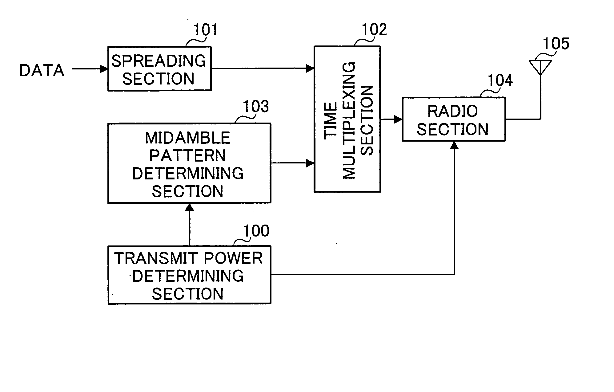
[0053]FIG. 8 is a block diagram showing a configuration of a mobile station apparatus equipped with a transmission apparatus according to Embodiment 1 of the present invention. In FIG. 8, transmit power determining section 100 calculates a propagation loss between this mobile station apparatus and a base station apparatus using a signal transmitted through an information channel (hereinafter referred to as “information channel signal”) Furthermore, transmit power determining section 100 determines a transmit power value of an RACH signal according to the calculated propagation loss and the number of times the RACH signal is retransmitted. The determined transmit power value is sent to midamble pattern determining section 103 and radio section 104.

[0054] Spreading section 101 performs spreading processing on the transmission data using a spreading code assigned to this mobile station apparatus. This transmission data corresponds to data subjected to predetermined modulation processi...

embodiment 2

[0104] This embodiment will explain a case where when a delay profile of a certain mobile station apparatus according to Embodiment 1 does not appear in an expected W-chip section, deterioration of channel estimated values of other mobile station apparatuses will be prevented. The mobile station apparatus equipped with a transmission apparatus according to this embodiment and the base station apparatus equipped with a reception apparatus according to this embodiment will be explained below focused on differences from Embodiment 1 with reference to FIG. 14 to FIG. 16.

[0105]FIG. 14 is a schematic view showing a procedure for creating midamble patterns used for mobile station apparatuses equipped with a transmission apparatus according to Embodiment 2 of the present invention. FIG. 15 is a schematic view showing transmission timing of the mobile station apparatuses equipped with the transmission apparatus according to Embodiment 2 of the present invention. FIG. 16 is a schematic view ...


PUM


Abstract

Transmit power determining section 100 determines a transmit power value based on the condition of the propagation path estimated from a propagation loss and the number of times the random access channel signal is retransmitted. Midamble pattern determining section 103 determines a midamble pattern corresponding to the transmit power value from among a plurality of midamble patterns. Time multiplexing section 102 creates a transmission signal by multiplexing transmission data subjected to spreading processing and the midamble pattern. Radio section 104 applies predetermined transmission processing to the transmission signal generated and transmits the transmission signal subjected to the transmission processing above using the determined transmit power value as a random access channel signal.

Description

TECHNICAL FIELD [0001] The present invention relates to a communication apparatus that cancels interference using matrix calculations in a CDMA (Code Division Multiple Access) based communication, and more particularly, to a communication apparatus that cancels interference during a random access communication. BACKGROUND ART [0002] One of conventional methods of extracting a demodulated signal by eliminating various kinds of interference such as interference due to multi-path fading, inter-symbol interference and multiple access interference is an interference signal elimination method using Joint Detection (hereinafter referred to as “JD”). This JD is disclosed in the “Zero Forcing and Minimum Mean-Square-Error Equalization for Multiuser Detection in Code-Division Multiple-Access Channels” (Klein A., Kaleh G. K., Baier P. W., IEEE Trans. Vehicular Technology, vol. 45, pp. 276-287, 1996.). [0003] This interference signal elimination method using JD is also used for a random access ...

Claims


Application Information

Patent Timeline
Patent Type & Authority Applications(United States)
IPC IPC(8): H04J13/00H04B1/10H04B1/7105H04B7/005H04B7/26H04W28/06H04W28/18H04W52/24H04W74/08H04W88/02
CPCH04B1/707H04B1/7105H04B2201/70701H04W52/50H04W52/325H04W52/48H04W52/242
Inventor KITADE, TAKASHIHAYASHI, MASAKI
Owner PANASONIC CORP
Why Eureka
Try Eureka