
Capillary tubing

a tubing and capillary technology, applied in the field of capillary tubing, can solve the problems of limited flexibility in the choice of jet dimensions, speed and jet material, and the tendency of pollution of the passageways in the supply system of target material, and achieve the effects of improving the pressure range, reducing the risk of nozzle damage, and ensuring the safety of the nozzl

Inactive Publication Date: 2005-08-11
JETTEC AB
View PDF4 Cites 3 Cited by
  • Summary
  • Abstract
  • Description
  • Claims
  • Application Information

AI Technical Summary

Benefits of technology

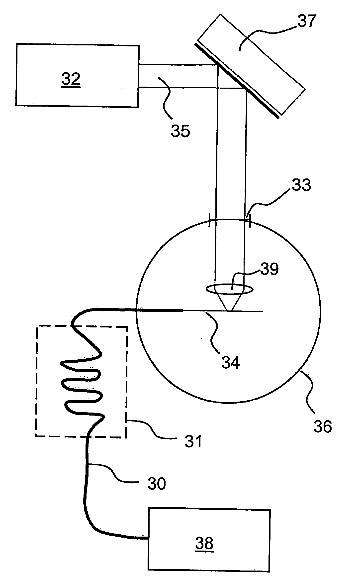
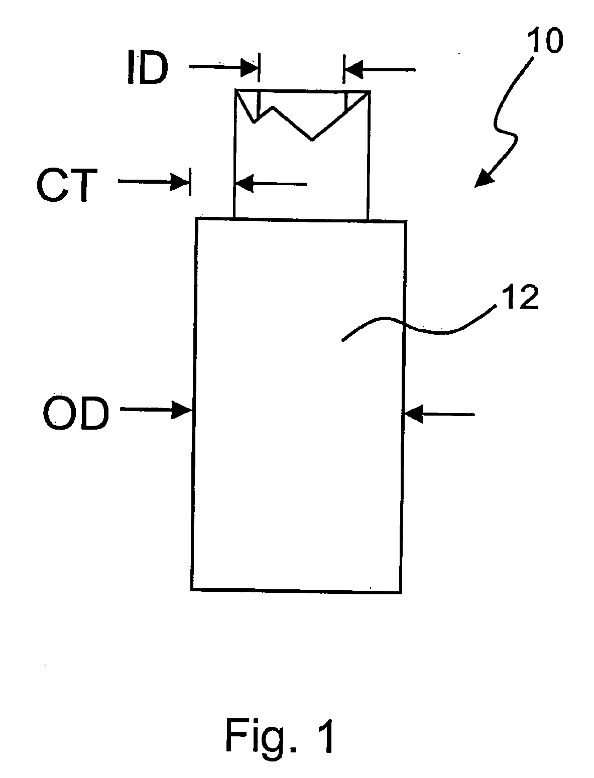
[0017] By employing a flexible capillary tubing of considerable length (typically longer than about 10 cm) for supplying target material to a jet-forming orifice inside an interaction chamber, wherein said orifice is an integral part of the capillary tubing, one or more of the following advantages are obtained:
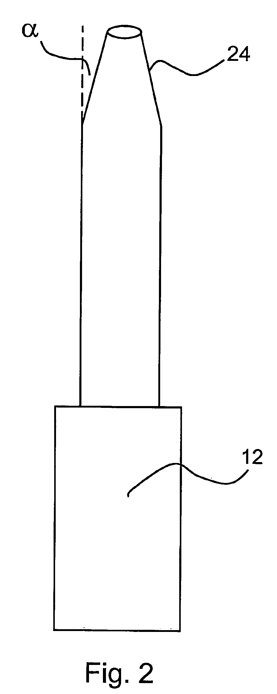
[0027] Hence, a flexible tubing for feeding target material between a reservoir and an interaction chamber is provided, wherein a jet-forming orifice is integrated with the capillary tubing. In addition to the advantages mentioned above, the flexible tubing with an orifice that is integral therewith leads to shorter manufacturing times for the tubing and orifice compared to prior art nozzles that are glued to a transport tube, and gives lower variable costs by allowing reuse of some parts of the system (e.g. filters).

Problems solved by technology

To this date, commercially available glass nozzles have primarily been used to produce the target jet, resulting in limited flexibility in the choice of jet dimensions, speed and jet material.
Unfortunately these nozzles have a fixed diameter and the range of usable target materials is limited since several interesting target materials have shown to dissolve some parts of the nozzle.
Other problems are associated with the prior art technology regarding the way the target material is supplied to the jet-forming nozzle.
Furthermore, when an organic material such as e.g. alcohols are employed, there is a tendency of pollution of the passageways in the supply system for the target material.
The reason is that many carbon based materials may dissolve parts of the equipment or seals used, such that the target material contains fragments or substances that may then clog the jet-forming nozzle.
This problem is accentuated by the numerous joints in the supply system for the target material.
Many inorganic materials, which may have aggressive properties, can lead to similar problems.
In addition, rather large volumes of target material must be handled and pressurized.
Furthermore, the target material must be kept at a desired pressure and temperature, which of course is rendered more difficult if dealing with large volumes.

Method used


Image

  • Capillary tubing
  • Capillary tubing
  • Capillary tubing

Examples


examples

[0046] In the following, some preferred implementations utilizing a capillary tubing according to the present invention will be described. Again, general reference is made to FIG. 3 of the accompanying drawings.

[0047] A first example of an arrangement in which a capillary tubing 30 is employed for supplying target material from a reservoir 38 of target material to a jet-forming orifice (not shown) in the interaction chamber 36 is based upon the advantage of online cooling. According to the present-invention, the container (or reservoir) 38 for target material is located outside the interaction chamber 36. In this particular example, the target material is nitrogen, which is to form a jet of target material in liquid state upon exit from the jet-forming orifice. The capillary tubing 30 is connected at one end to the target material reservoir 38. At the other end of the capillary, an orifice is formed in the manner described above. The capillary 30 has a length of about 50 cm and pas...


PUM

PropertyMeasurementUnit
lengthaaaaaaaaaa
lengthaaaaaaaaaa
inner diameter IDaaaaaaaaaa

Abstract

A method and an arrangement for generating x-ray or EUV radiation are disclosed. Target material is supplied from a container for target material to a jet-forming orifice in an interaction chamber by means of a flexible capillary tubing of considerable length, wherein the orifice is an integral part of the capillary tubing. A jet formed by urging target material through the orifice is made to interact with a beam of energy, thus producing a radiating plasma emitting the desired electromagnetic radiation. The use of a flexible capillary tubing for supplying target material from a source of target material to an orifice, which is integrated with the tubing, within an interaction chamber, in order to form therein a jet of target material for interaction with an energy beam to generate x-ray or EUV radiation, is also disclosed.

Description

TECHNICAL FIELD OF THE INVENTION [0001] The present invention relates to a method and an arrangement for generating x-ray or EUV radiation from laser produced plasmas. The invention also relates to use of capillary tubing in such method and arrangement. TECHNICAL BACKGROUND [0002] X-ray and EUV sources based on emission from a laser produced plasma in a target jet are becoming increasingly important since they provide a high-density regenerative target in combination with negligible debris operation. To this date, commercially available glass nozzles have primarily been used to produce the target jet, resulting in limited flexibility in the choice of jet dimensions, speed and jet material. [0003] X-ray and EUV sources of the above-mentioned kind feature high flux and brightness, allow long-term operation without interruption and emit narrow bandwidth radiation appropriate for zone-plate optics. Furthermore spectrally tailored emission for a specific application can be produced by se...

Claims


Application Information

Patent Timeline
Patent Type & Authority Applications(United States)
IPC IPC(8): H01L21/027H05G2/00G21K5/08
CPCH05G2/006H05G2/003
Inventor JOHANSSON, GORANHERTZ, HANSDE GROOT, JACO
Owner JETTEC AB
Learn More