[0010] According to another object of the present invention, the
control system operates the motor / brake unit in its motor mode when the speed of one of the rotary members is less than a predetermined threshold speed value so as to drive a rotor of the motor / brake unit which causes axial movement of an output member of the torque / force conversion mechanism. The
control system switches the motor / brake unit into its brake mode when the rotary speed exceeds the threshold speed value so as to apply a dynamic
brake torque to the rotor for controlling axial movement of the output member of the torque / force conversion mechanism. In addition, the present invention provides a clutch actuator assembly utilizing a low
torque motor which acts as an
electric generator so as to significantly reduce the electrical power requirements needed to adaptively
control torque transfer through the clutch assembly.
[0012] In accordance with another objective of the present invention, the
control system is provided for use in driveline applications equipped with two or more torque couplings that are operable to control coordinated actuation of each
electric motor / brake unit. In particular, switching each of the motor / brake units between operation in their motor and brake
modes permits regenerated electrical power to be used, thereby significantly reducing the electrical power requirements from the vehicle's host
system.
[0015] In accordance with a first embodiment, the drive axle assembly of the present invention includes first and second axleshafts and a torque distributing drive mechanism that is operable to selectively couple a driven input shaft to one or both of the axleshafts. The drive mechanism includes a differential assembly, a planetary gear assembly, and first and second torque couplings. The planetary gear assembly is operably disposed between the differential assembly and the first axleshafts. The first torque
coupling is operable in association with the planetary gear assembly to increase the rotary speed of the first axleshaft which, in turn, causes the differential assembly to decrease the rotary speed of the second axleshaft. In contrast, the second torque
coupling is operable in association with the planetary gear assembly to decrease the rotary speed of the first axleshaft so as to cause the differential assembly to increase the rotary speed of the second axleshaft. Accordingly,
selective control over actuation of one or both of the first and second torque couplings provides
adaptive control of the speed differentiation and the torque transferred between the first and second axleshafts.
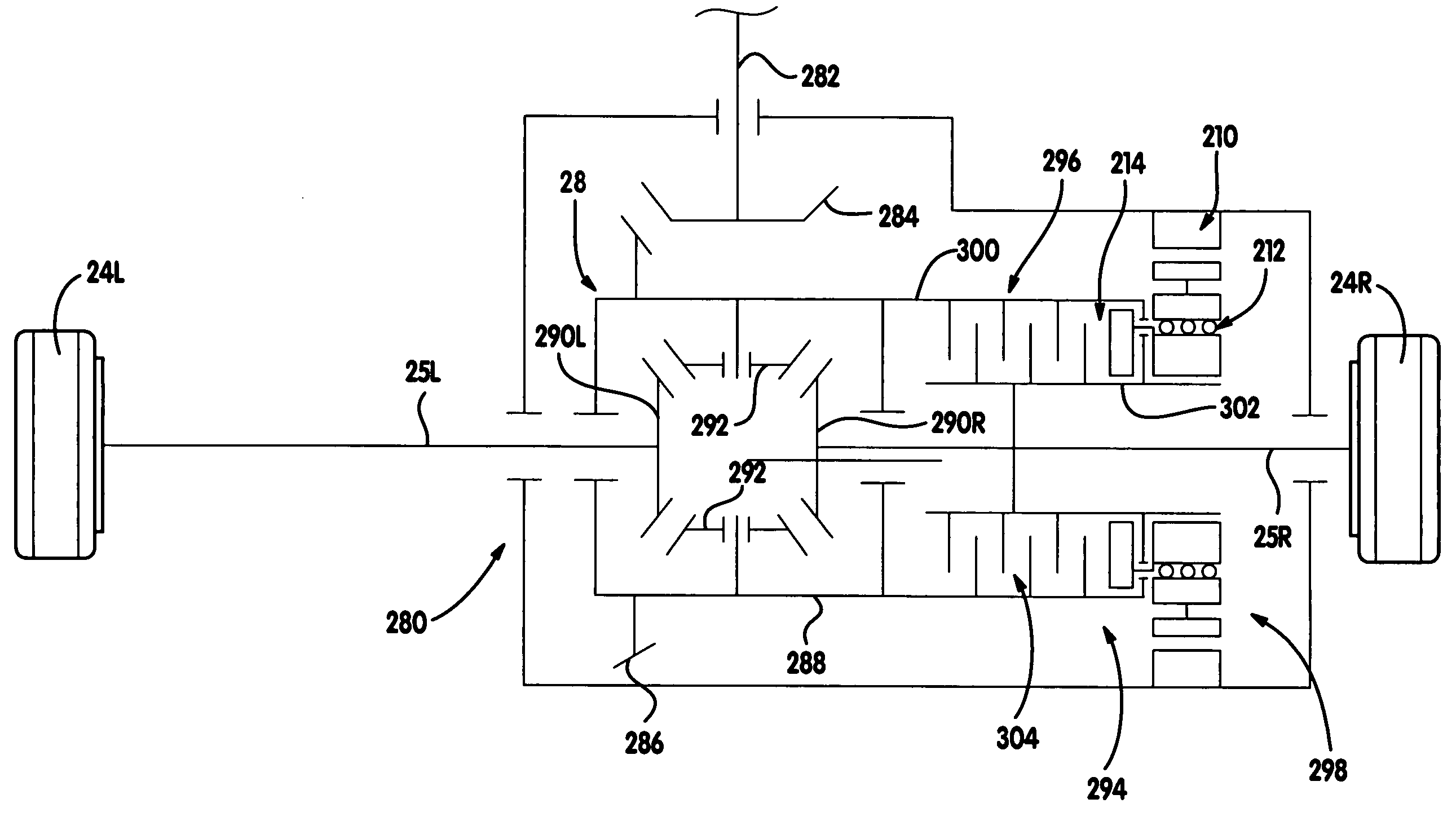
[0016] According to a second embodiment, the drive axle assembly of the present invention includes first and second axleshafts and a torque distributing drive mechanism that is operable for transferring drive torque from a driven input shaft to the first and second axleshafts. The torque distributing drive mechanism includes a differential, first and second speed changing units, and first and second torque couplings. The differential includes an input component driven by the input shaft, a first output component driving the first axleshaft and a second output component driving the second axleshaft. The first speed changing unit includes a first planetary gearset having a first sun gear driven by the first output component, a first ring gear, and a set of first
planet gears rotatably supported by the input component and which are meshed with the first ring gear and the first sun gear. The second speed changing unit includes a second planetary gearset having a second sun gear driven by the second output component, a second ring gear, and a set of second
planet gears rotatably supported by the input component and which are meshed with the second ring gear and the second sun gear. The first torque
coupling is operable for selectively braking rotation of the first ring gear. Likewise, the second torque coupling is operable for selectively braking rotation of the second ring gear. Accordingly,
selective control over actuation of the first and second torque couplings provides
adaptive control of the speed differentiation and the torque transferred between the first and second axleshafts.
[0018] In accordance with a fourth embodiment, a drive axle assembly according to the present invention includes first and second axleshafts and a torque distributing drive mechanism that is operable for transferring drive torque from a driven input shaft to the first and second axleshafts. The torque distributing drive mechanism includes a differential, first and second speed changing units, and first and second torque couplings. The differential includes an input component driven by the input shaft, a first output component driving the first axleshaft and a second output component driving the second axleshaft. The first speed changing unit includes a first planetary gearset having a first
planet carrier driven with the first output component, a first ring gear driven by the input component, a first sun gear, and a set of first planet gears rotatably supported by the first planet carrier and which are meshed with the first ring gear and the first sun gear. The second speed changing unit includes a second planetary gearset having a second planet carrier driven with the second output component, a second ring gear driven by the input component, a second sun gear, and a set of second planet gears rotatably supported by the second planet carrier and which are meshed with the second ring gear and the second sun gear. The first torque coupling is operable for selectively braking rotation of the first sun gear. Likewise, the second torque coupling is operable for selectively braking rotation of the second sun gear. Accordingly,
selective control over actuation of the first and second torque couplings provides
adaptive control of the speed differentiation and the torque transferred between the first and second axleshafts.
[0019] According to a fifth embodiment, the drive axle assembly of the present invention includes first and second axleshafts and a torque distributing drive mechanism that is operable for transferring drive torque from a driven input shaft to the first and second axleshafts. The torque distributing drive mechanism includes a differential, a speed changing unit, and first and second torque couplings. The differential includes an input component driven by the input shaft, a first output component driving the first axleshaft and a second output component driving the second axleshaft. The speed changing unit includes a first shaft commonly driven with the first axleshaft, a second shaft commonly driven with the second axleshaft, and first and second gearsets driven by the first shaft. The first torque coupling is operable for selectively coupling the first gearset to the second shaft. Likewise, the second torque coupling is operable for selectively coupling the second gearset to the second shaft. Accordingly, selective control over actuation of one or both of the first and second torque couplings provides adaptive control of the speed differentiation and the torque transferred between the first and second axleshafts.

