
Analyzer having information recognizing function, analytic tool for use therein, and unit of analyzer and analytic tool

Inactive Publication Date: 2005-08-18
ARKRAY INC
View PDF4 Cites 14 Cited by
  • Summary
  • Abstract
  • Description
  • Claims
  • Application Information

AI Technical Summary

Benefits of technology

[0010] The present invention also aims at reducing deterioration in part of the analyzer where the information from the analyzing article is recognized.
[0011] Further, the present invention aims at enabling the analyzer to recognize the information from the analyzing article without very much sacrificing freedom in the design of the analyzer.

Problems solved by technology

Especially, when starting up the production line, due to needs for optimizing various conditions in the production line and selecting suitable materials, sensitivity variations among the produced sensors tend to be large.
A first problem relates to manufacturing of the biosensors due to an arrangement that the production-lot identifying electrodes are formed on the same side of a substrate on which measuring electrodes are formed.
A challenge in this case is that the sensitivity of the biosensor must be forecasted and the production-lot identifying electrodes must be formed on the forecast.
If a large discrepancy is found between the actual sensor sensitivity and the forecast sensitivity, the produced biosensors must be scrapped, resulting in decreased yield.
If the measuring electrodes and the production-lot identifying electrodes are formed in separate steps, then the steps for forming the production-lot identifying electrodes are extra steps involving complex operations such as screen printing or vapor depositing, which will decrease operation efficiency.
A second problem relates to construction.
This contact is made every time the biosensor is attached to the measuring device, making the identification terminals prone to deterioration.
If the identification terminals are prone to deterioration, the measuring device must be repaired or serviced frequently, or the deterioration itself shortens the life of the device.
A third problem relates to the measuring device itself, due to the fact that the production-lot identifying electrodes are formed on the same side of the substrate on which the measuring electrodes are formed.
This means that all of these electrodes must be disposed in a very small area under very tight limitations.
This poses significant limitations in designing the part of measuring device to which the biosensor is attached, decreasing freedom in design.
Such a problem becomes more conspicuous as the number of identifying terminals increases with increasing amount of information to be recognized by the measuring device.

Method used


Image

  • Analyzer having information recognizing function, analytic tool for use therein, and unit of analyzer and analytic tool
  • Analyzer having information recognizing function, analytic tool for use therein, and unit of analyzer and analytic tool
  • Analyzer having information recognizing function, analytic tool for use therein, and unit of analyzer and analytic tool

Examples


first embodiment

[0058] First, a first embodiment will be described.

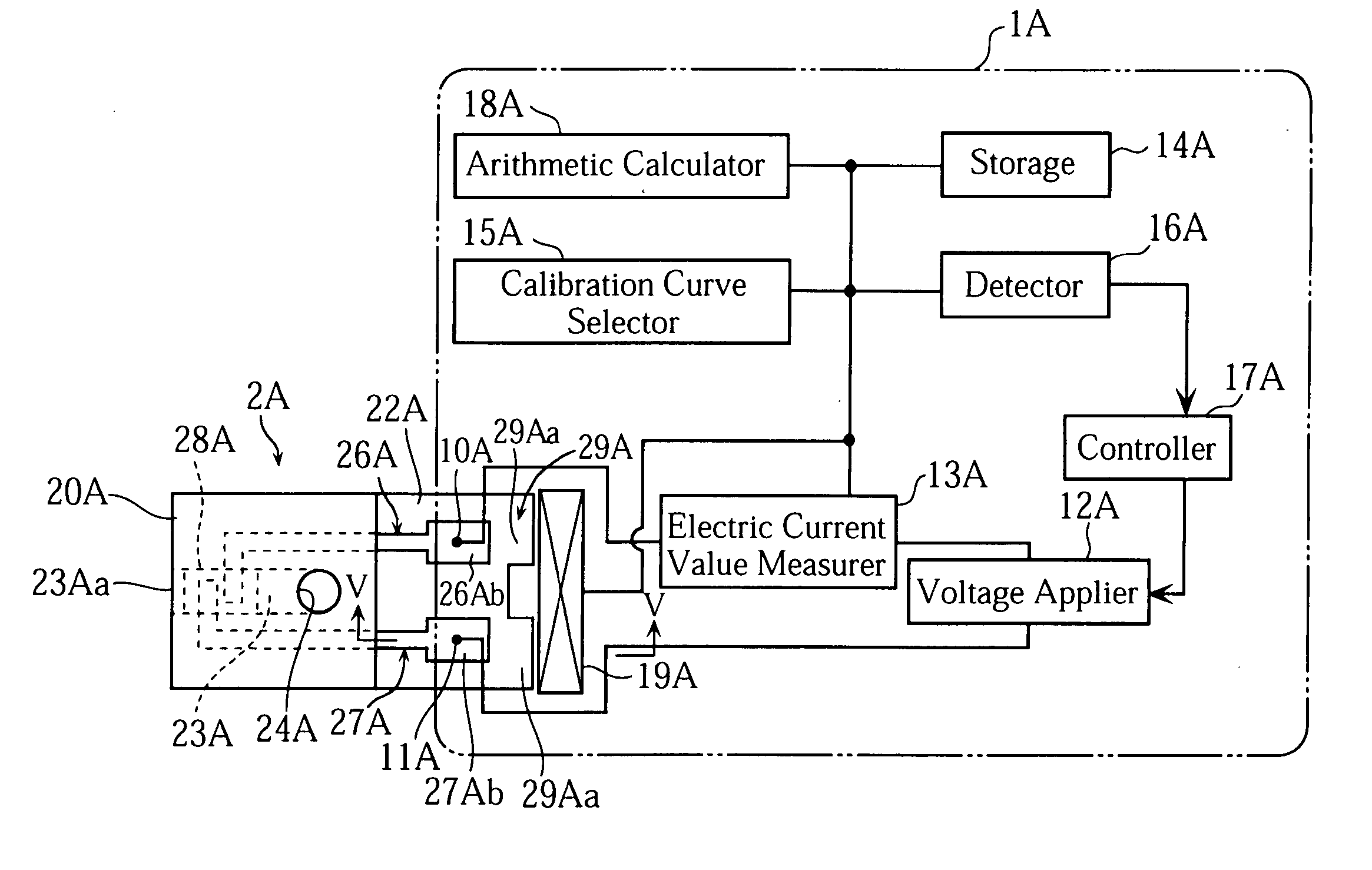
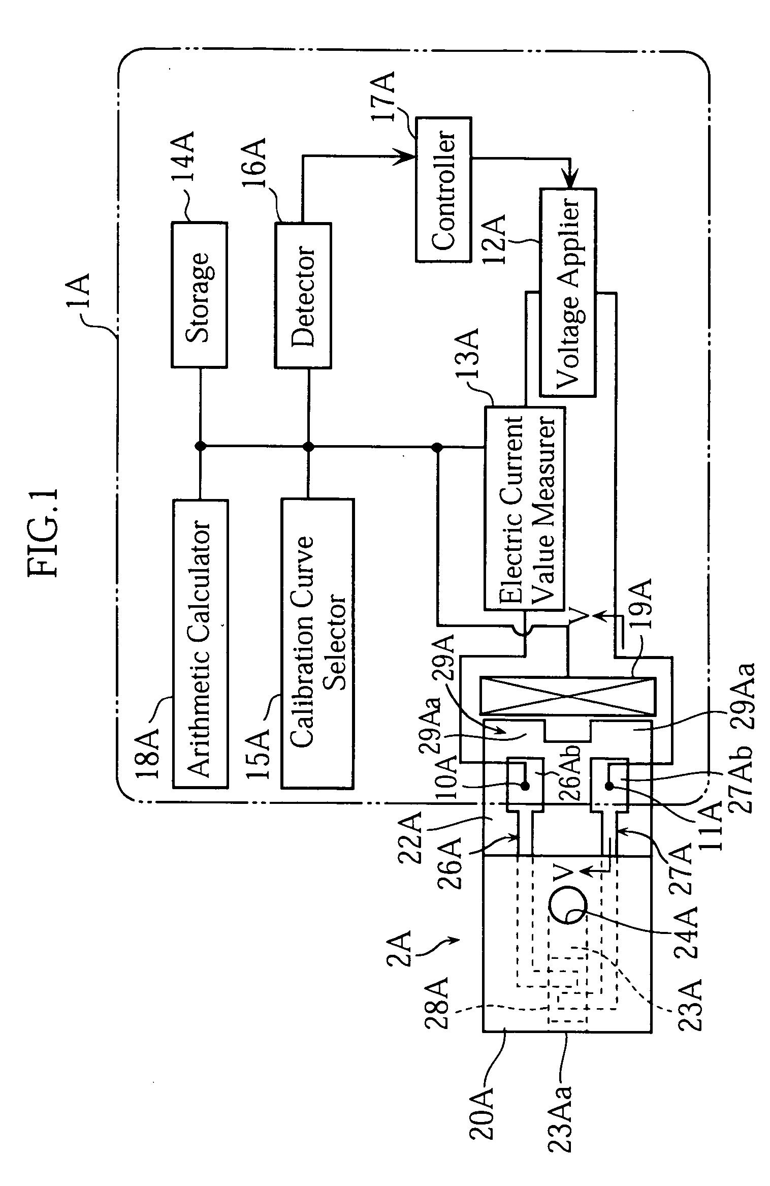
[0059] As shown in FIG. 1, an analyzer 1A uses a biosensor 2A. The analyzer 1A is capable of performing an electrochemical measurement on the concentration of a specific component in a sample fluid supplied to the biosensor 2A.

[0060] The analyzer 1A generally includes measuring terminals 10A, 11A, a voltage applier 12A, an electric current value measurer 13A, a storage 14A, a calibration curve selector 15A, a detector 16A, a controller 17A, an arithmetic calculator 18A and an information recognizer 19A. Details of the components 10A-19A will be described later.

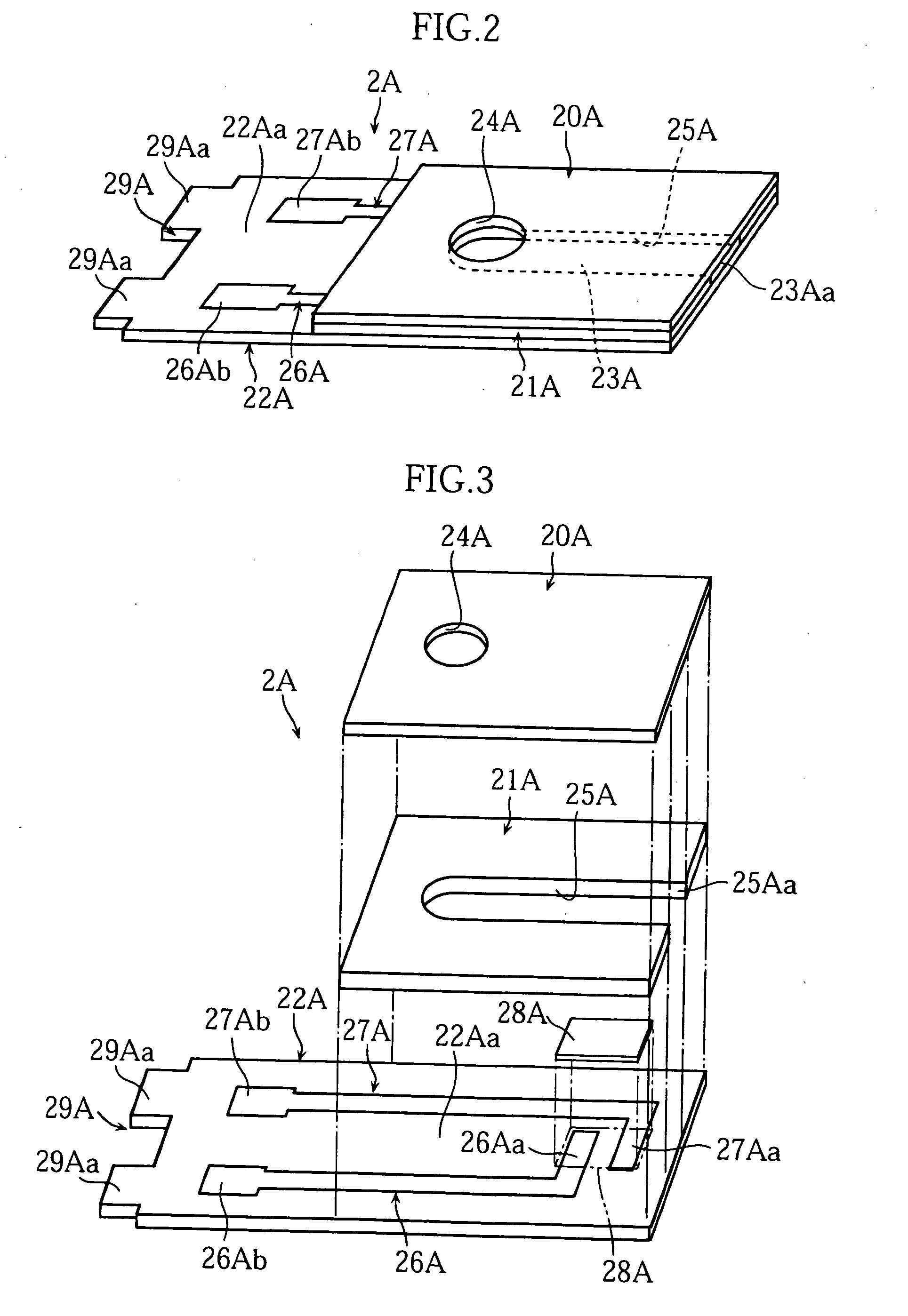
[0061] The biosensor 2A, on the other hand, includes a cover 20A, a spacer 21A and a substrate 22A as clearly shown in FIG. 1 through FIG. 3, and these components provide a passage 23A.

[0062] The cover 20A has a hole 24A in order to allow gas in the passage 23A to escape. The spacer 21A has a slit 25A. The slit 25A determines the size of the passage 23A and has an open end ...

second embodiment

[0094] Next, the present invention will be described with reference to FIG. 11 as well as FIG. 12A and FIG. 12B.

[0095] In a biosensor 2B in FIG. 11, a quantity (including zero) of projections 29Bb and locations of the projections 29Bb represent information to be recognized by an analyzer 1B in FIG. 12A and FIG. 12B. The projections 29Bb are hemispheres projecting from a back surface of a substrate 22B. Projections such as the projections 29Bb offer advantages, for example, that the user can easily tell the top and the back surfaces of the biosensor 2B, and the biosensor 2B can be easily picked or removed when it is placed on a flat surface like a table.

[0096] The projections 29Bb can be formed, for example, by first preparing a thermoplastic resin in a molten or a pasty form softened with a solvent, potting and then allowing the resin to set on the back surface of the substrate 22B. Such an operation is significantly easier than screen printing or vapor depositing, and thus the add...

third embodiment

[0100] Next, the present invention will be described with reference to FIG. 13A and FIG. 13B.

[0101] A biosensor 2A shown in FIG. 13A and FIG. 13B is the same as the one used in the first embodiment (See FIG. 2 through FIG. 4). Specifically, the biosensor 2A includes a substrate 22A having an end having specific regions where projections 29Aa can be made. By selecting whether to form a projection 29Aa or not, for each of the three regions, information is assigned for recognition by the analyzer 1C.

[0102] On the other hand, the analyzer 1C shown in the same figures differs from those used in the first and the second embodiments, in the construction of information recognizer 19C. Though not illustrated very much clearly in the Figures, the information recognizer 19C has three capacity sensors 190C. Each capacity sensor 190C has a first and a second electrodes 195C, 196C, and the first and the second electrodes 195C, 196C can make a relative movement to each other in a direction in whi...


PUM

PropertyMeasurementUnit
Currentaaaaaaaaaa
Currentaaaaaaaaaa
Currentaaaaaaaaaa

Abstract

The present invention relates to an analyzer (1A) used with an analyzing article (2A) attached thereto, for analysis of a specific component in a sample liquid supplied to the analyzing article (2A). The analyzer (1A) includes an information recognizer for recognition of information added to the analyzing article. The information recognizer includes an electro-physical-quantity variable part (190A) which has different electro-physical quantities in accordance with the information added to the analyzing article (2A) when the analyzing article (2A) is attached. The analyzing article (2A) includes an information carrier (29A) for giving information to the analyzer (1A). The information carrier (29A) provided by a projection or a hole related to the information to be recognized by the analyzer (1A).

Description

TECHNICAL FIELD [0001] The present invention relates to the technology for analyzing a specific component in a sample. More specifically, the present invention relates to an analyzing article used in analysis of a sample, an analyzer, and a unit of the analyzing article and the analyzer. BACKGROUND ART [0002] As a common method of measuring a specific component in the body fluid such as glucose in the blood, an oxidation-reduction reaction promoted by an oxidation-reduction enzyme is utilized. On the other hand, for handy measurement of the blood sugar levels at home and elsewhere, palm-size, portable blood sugar level testers are used widely. These handy-type blood sugar level testers make use of disposable biosensors, which also provides an enzyme reaction field. The blood sugar level measurement is made by supplying the blood to the biosensor. [0003] Sensitivity of the individual biosensors can vary from one biosensor to another. The variation can be a result of difference in row...

Claims


Application Information

Patent Timeline
IPC IPC(8): G01N33/487
CPCG01N33/48771
Inventor KOBAYASHI, TAIZO
Owner ARKRAY INC
Features
  • Generate Ideas
  • Intellectual Property
  • Life Sciences
  • Materials
  • Tech Scout
  • Unparalleled Data Quality
  • Higher Quality Content
  • 60% Fewer Hallucinations
Learn More