Rotary electric apparatus with skew arrangement

a rotary electric and skew arrangement technology, applied in the direction of magnetic circuit rotating parts, magnetic circuit shape/form/construction, stator/rotor body manufacturing, etc., can solve the problem that the conventional skew arrangement structure is insufficient for cancelling the torque harmonic components, and achieve the effect of suppressing the reduction of effective torqu

Active Publication Date: 2005-08-18
DENSO CORP
View PDF15 Cites 40 Cited by
  • Summary
  • Abstract
  • Description
  • Claims
  • Application Information

AI Technical Summary

Benefits of technology

[0019] Accordingly, the shifts of the phase angles at both the rotor members, which are measured from the phase angle of zero at which the torque zero-th component shows its maximum, can

Problems solved by technology

However, it has been pointed out that such conventional skew arrangement

Method used


Image

  • Rotary electric apparatus with skew arrangement
  • Rotary electric apparatus with skew arrangement
  • Rotary electric apparatus with skew arrangement

Examples


first embodiment

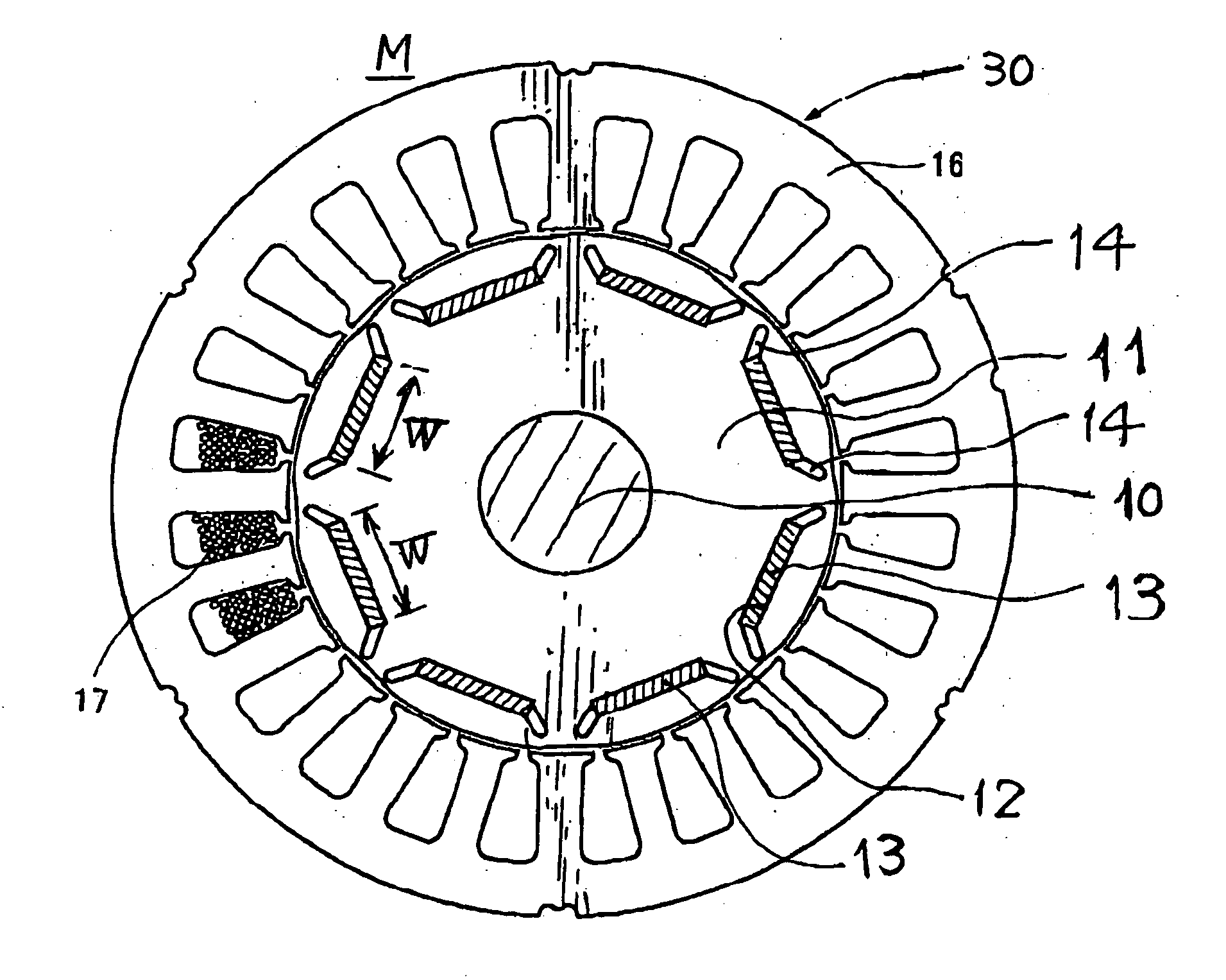
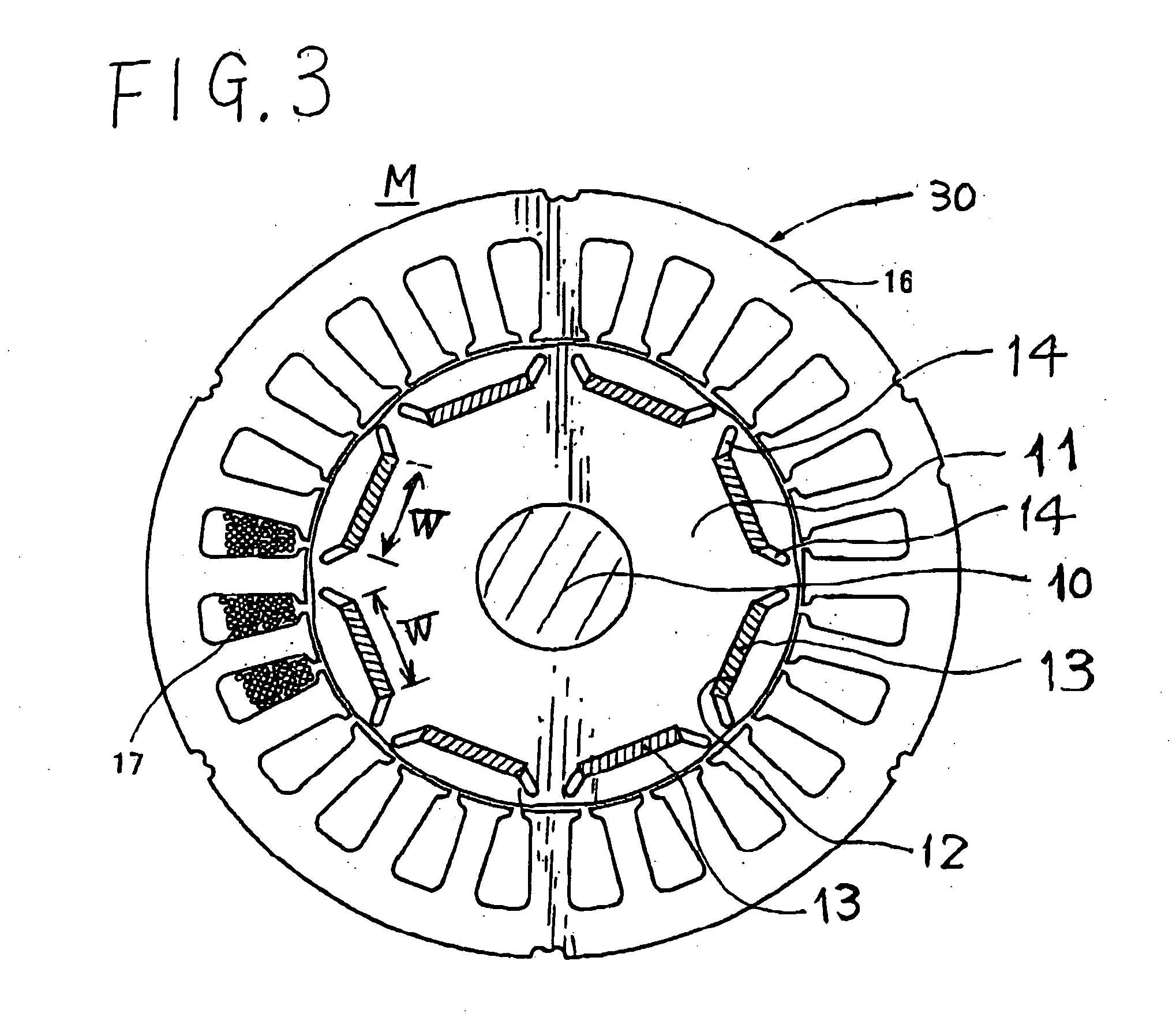
[0038] Referring to FIGS. 1 to 4, a first embodiment of the rotary electric apparatus according to the present invention will now be described.

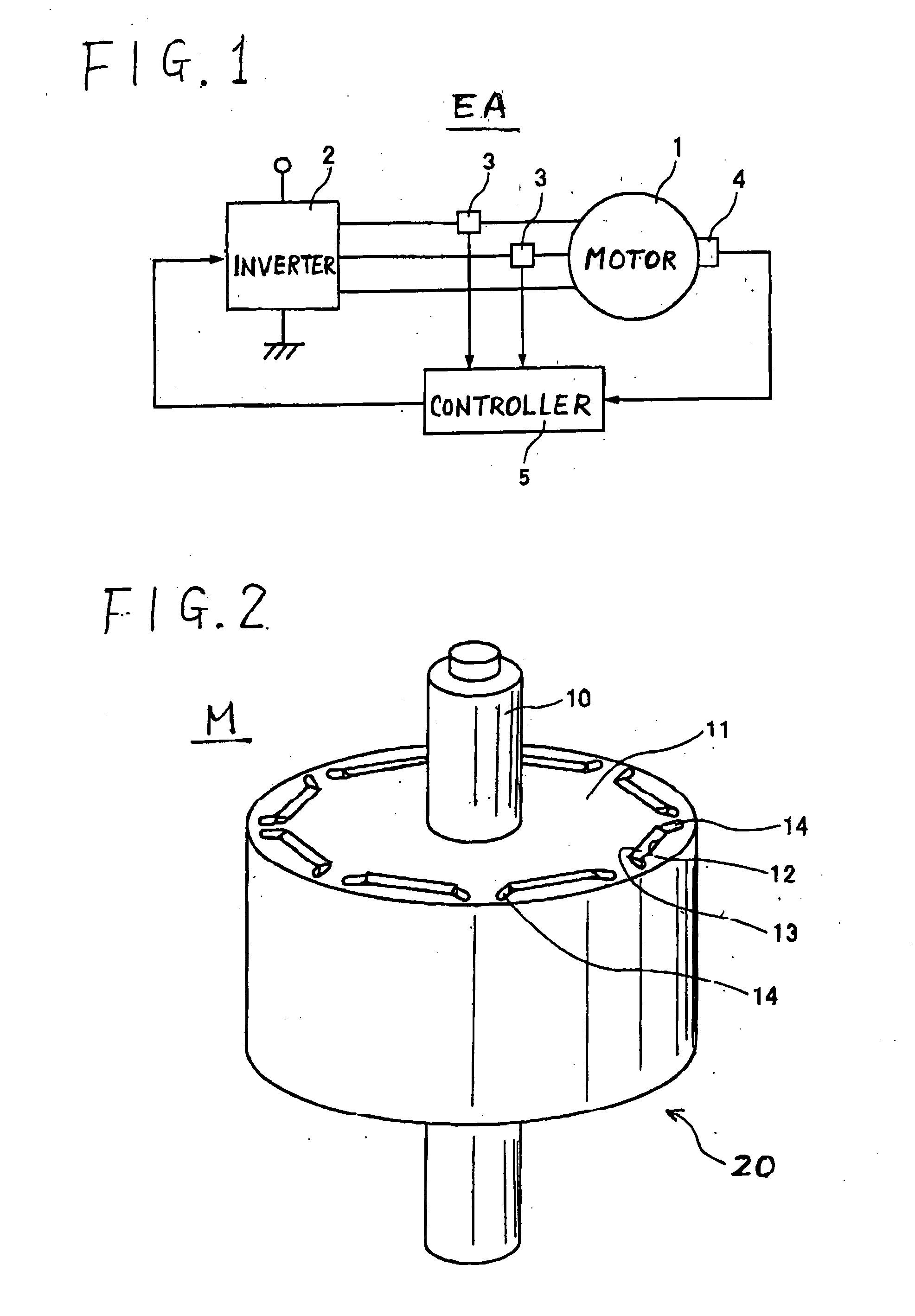
[0039]FIG. 1 schematically outlines the electrical configuration of an electric apparatus EA in which a synchronous machine 1 serving as the rotary electric apparatus according to the present invention is incorporated. In the present invention, the synchronous machine 1 is of a magnetic rotor (usually called “IPM (Interior Permanent Magnet)” type of machine and, by way of example, is composed of a brushless DC (direct current) motor of IPM type, but this is not a definitive list.

[0040] This electronic apparatus EA is provided with, in addition to the IPM type of synchronous machine 1, an inverter 2, current sensors 3, a rotation angle sensor 4, and a controller 5. The elements 2-5 constitute the armature current controller for the synchronous machine 1.

[0041] The inverter 2 is in charge of converting DC (direct current) power, which is sup...

first modification

[0059] A first modification relates to the order of a harmonic component of torque caused between the rotor and stator member. This order will not be confined to the sixth order, but any other orders are to be targeted for the cancellation of their harmonic components.

second modification

[0060] A second modification is depicted in FIG. 5. In this modification, the rotor 20 is formed by, for example, three groups of segments 20a, 20b and 20c, in which each segment group 20a (20b, 20c) is composed of the first member pair “F” consisting of the first rotor member 21 and the first stator member 31 and the second member pair “S” consisting of the second rotor member 22 and the second stator member 32. Each of the members 21, 22, 31 and 32 is identical to that described in FIG. 4(A). These three groups of segments 20a, 20b and 20c are mounted on the rotation shaft 10 in the axial direction thereof in a mutually juxtaposed manner.

[0061] This manner of arrangement is effective in reducing variations of torque (i.e., unbalance of torque) generated between each rotor / stator member pair disposed along the axial direction of the rotation shaft 10, because the first and second rotor members 21 and 22, which produce mutually different amounts of torque with the aid of the first ...


PUM


Abstract

A rotary electric apparatus comprises a rotor including a first and second rotor members, a stator including a first stator and second stator members with armature coils to which armature current is supplied for synchronous rotation. The first and second rotor members are formed into a skewed type. Control means for controlling amounts Φ1 and Φ2 of field magnetic flux generated by the first and second rotor members, respectively, such that the amounts Φ1 and Φ2 differ from each other to reduce a difference between a maximum amplitude of a predetermined-order harmonic component F1 of an electromagnetic force caused by a pair of the first rotor member and the first stator member and a maximum amplitude of the predetermined-order harmonic component F2 of an electromagnetic force caused by a further pair of the second rotor member and the second stator member is reduced.

Description

CROSS REFERENCES TO RELATED APPLICATIONS [0001] The present application relates to and incorporates by reference Japanese Patent application No. 2004-16346 filed on Jan. 23, 2004. BACKGROUND OF THE INVENTION [0002] 1. Field of the Invention [0003] The present invention relates to a rotary electric apparatus, such as DC brushless motor and three-phase AC motor generator, which is generally called “synchronous machine,” and, in particular to the rotary electric apparatus which has an improved ability to reduce the ripples of torque that are generated and also reduce the noise (called “magnetic noise”) caused by pulsated drive current. [0004] 2. Description of the Related Art [0005] A various types of rotary electric apparatuses have now been used, one type of which is proposed by (i) Japanese Patent publication No. 2672178, (ii) Japanese Patent publication No. 3028669, (iii) Japanese Patent Laid-open publication No. 9-182387, and (iv) Japanese Patent Laid-open publication No. 2003-284...

Claims


Application Information

Patent Timeline
IPC IPC(8): H02K15/02H02K1/27H02K16/00H02K17/00H02K19/22H02K21/12H02K21/14H02K29/03
CPCH02K21/14H02K2201/06H02K29/03
Inventor YOSHINAGA, SOICHI
Owner DENSO CORP
Why Eureka
Try Eureka