

Radar device for obtaining position data
a technology for obtaining position data and radar devices, which is applied in the direction of measurement devices, using reradiation, instruments, etc., can solve the problems of increasing the cost of the apparatus and also the operational cost, and the inability to detect the position and the size of objects in the direction of the scan with a better accuracy
- Summary
- Abstract
- Description
- Claims
- Application Information
AI Technical Summary
Benefits of technology
Problems solved by technology
Method used
Image

Examples
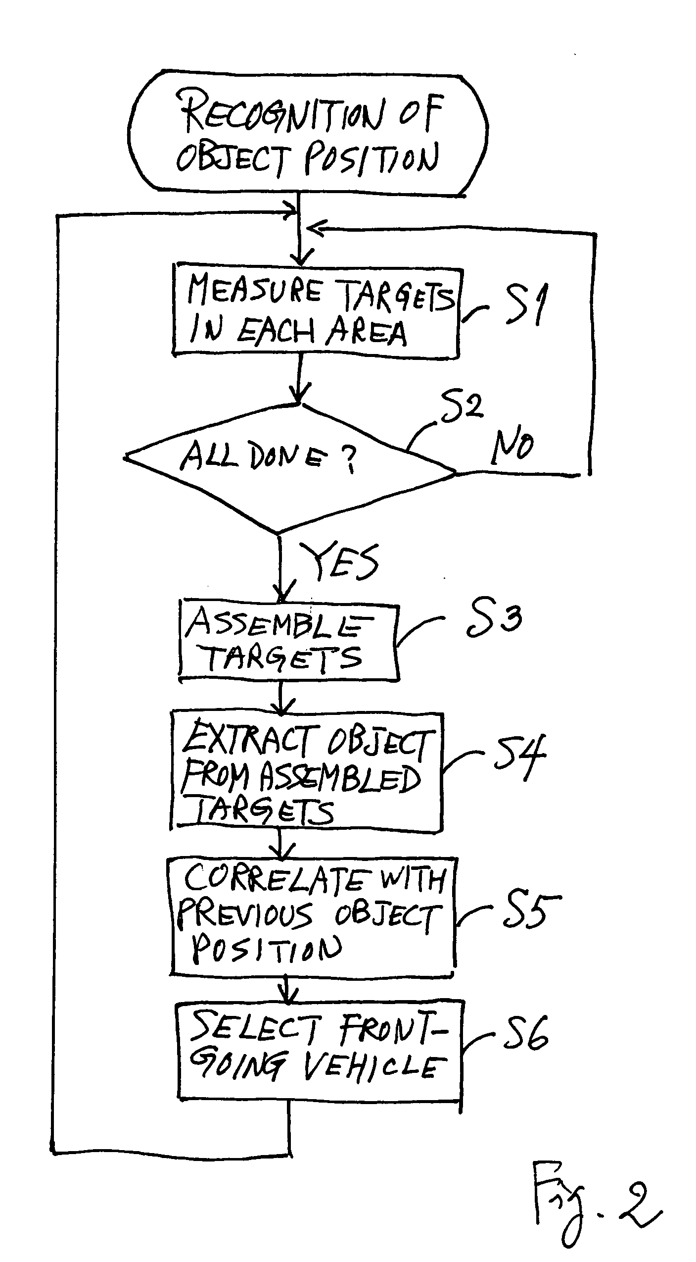
first embodiment
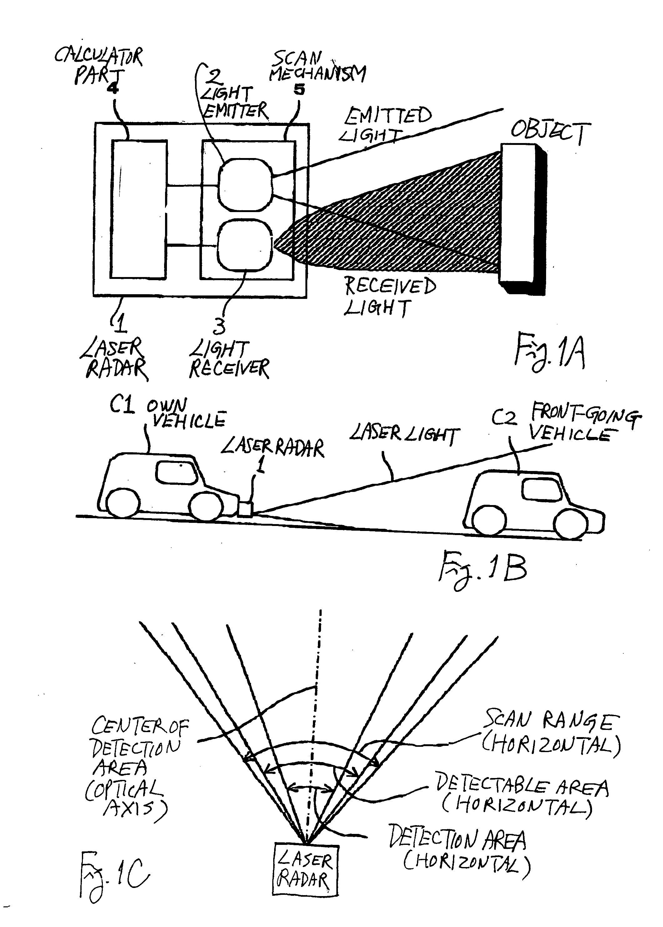
[0041]FIGS. 1A, 1B and 1C, together referred to as FIG. 1, are for explaining a radar device 1 for a vehicle according to the invention, FIG. 1A showing the structure of the device, FIG. 1B showing the device as set on a vehicle and FIG. 1C showing the relationship between its detection area and its scan range.
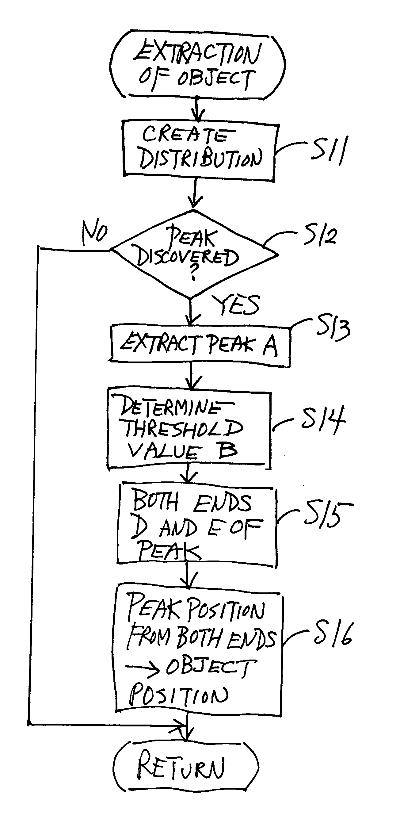
[0042] The radar device 1 shown in FIG. 1 is a laser radar device of a pulse echo type and comprises a light emitter 2, a light receiver 3, a calculator part 4 and a scan mechanism 5. The calculator part 4 in this example serves as aforementioned waveform setting means, peak extracting means, threshold setting means, end position judging means and center position judging means.
[0043] The light emitter 2 includes a radar transmitter head having a laser diode LD and its optical system and a driver circuit for the laser diode. The light receiver 3 includes a radar receiver head having a photodiode PD and its optical system and a light receiving circuit for processing the output ...
second embodiment
[0073] According to the invention, as shown in FIG. 7, Steps S21-S22 (instead of Steps S13-S16) are carried out if it is judged in Step S12 that there is a peak (YES in Step S12). In Step S21, a continuous waveform is set and received light quantity data of the peak are extracted. If the received light quantity data are as shown in FIG. 8A, a continuous waveform may be drawn as shown in FIG. 8B as a curve (estimated distribution curve B) interpolating the data points as defined above with reference to FIG. 4B. In general, a curve passing through a plural number N of points may be expressed by a polynomial of order N-1. Thus, if N is the number of data points, a polynomial of order N-1 can be obtained by solving N-number of simultaneous equations to obtain a curve that passes through all these data points.
[0074] If it is desirable to reduce the load on the CPU for solving many simultaneous equations, a curve between a pair of mutually adjacent data points may be drawn by solving for ...
PUM
 Abstract
Description
Claims
Application Information