Lithographic apparatus and device manufacturing method with feed-forward focus control

a technology of focus control and lithographic equipment, applied in the direction of gravity apparatus, photographic process, radiation therapy, etc., can solve the problems of limited performance and non-optimal focusing, and achieve the effect of reliable focus control, reducing inevitable position, speed, acceleration etc. errors, and reducing the effect of inevitable position, speed, acceleration,

Active Publication Date: 2005-08-18
ASML NETHERLANDS BV
View PDF17 Cites 27 Cited by
  • Summary
  • Abstract
  • Description
  • Claims
  • Application Information

AI Technical Summary

Benefits of technology

[0022] Preferably, the reference plane is substantially parallel oriented to the supporting surface of the substrate table, wherein the reference plane can have a fixed position with respect to the projection system. The later guarantees that the distances of the surface are determined with respect to the projection system, such that the surface information (“height map”) can be related to the projection system thereby enabling a reliable focus control.
[0023] One embodiment is characterized in that the second support structure comprises a second substrate table, wherein the lithographic apparatus is constructed and arranged to measure with the level sensor surface information of a substrate placed on the second substrate table, while exposing another substrate placed on the said substrate table which is thereby position

Problems solved by technology

Such a configuration results in limited

Method used


Image

  • Lithographic apparatus and device manufacturing method with feed-forward focus control
  • Lithographic apparatus and device manufacturing method with feed-forward focus control
  • Lithographic apparatus and device manufacturing method with feed-forward focus control

Examples


embodiments

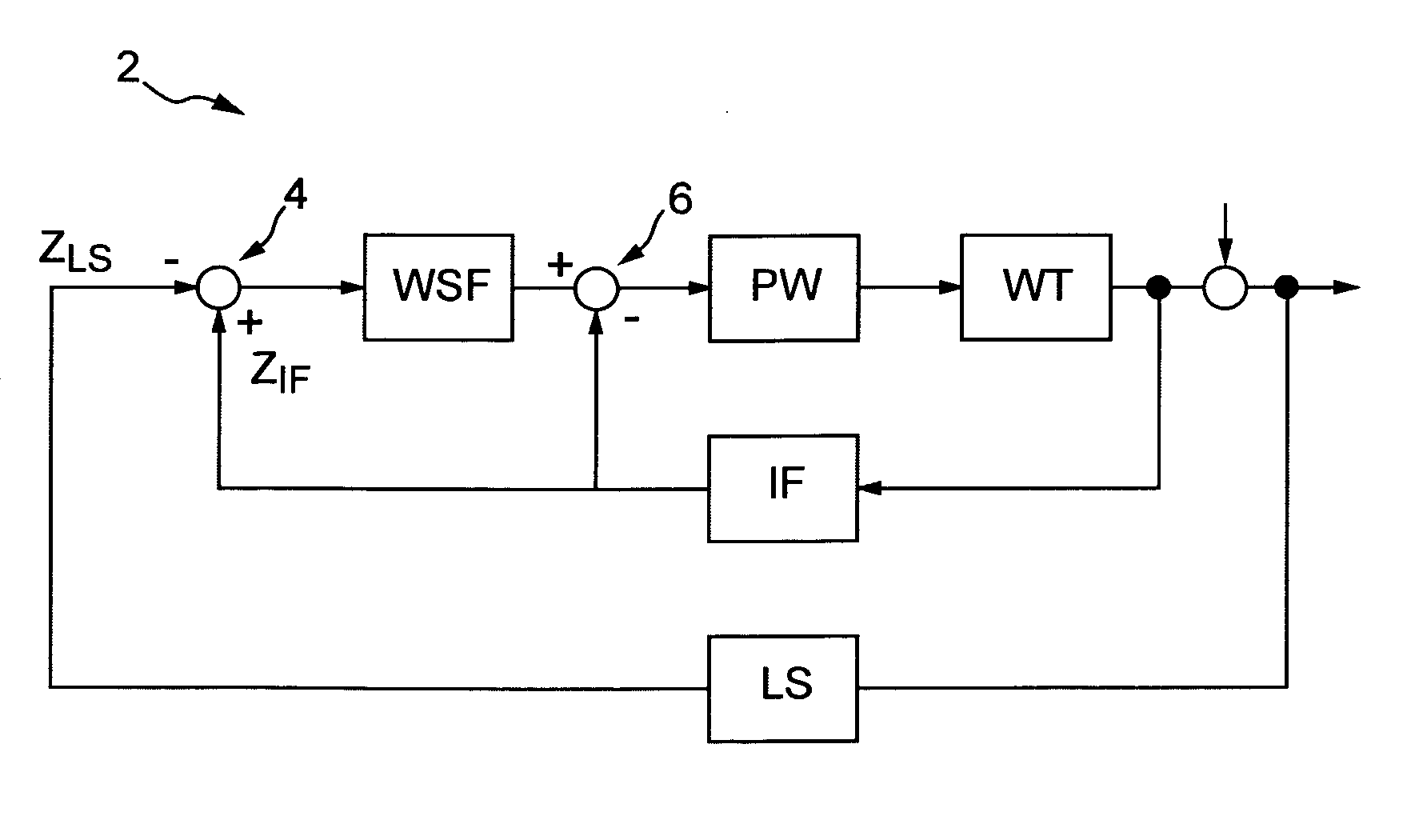
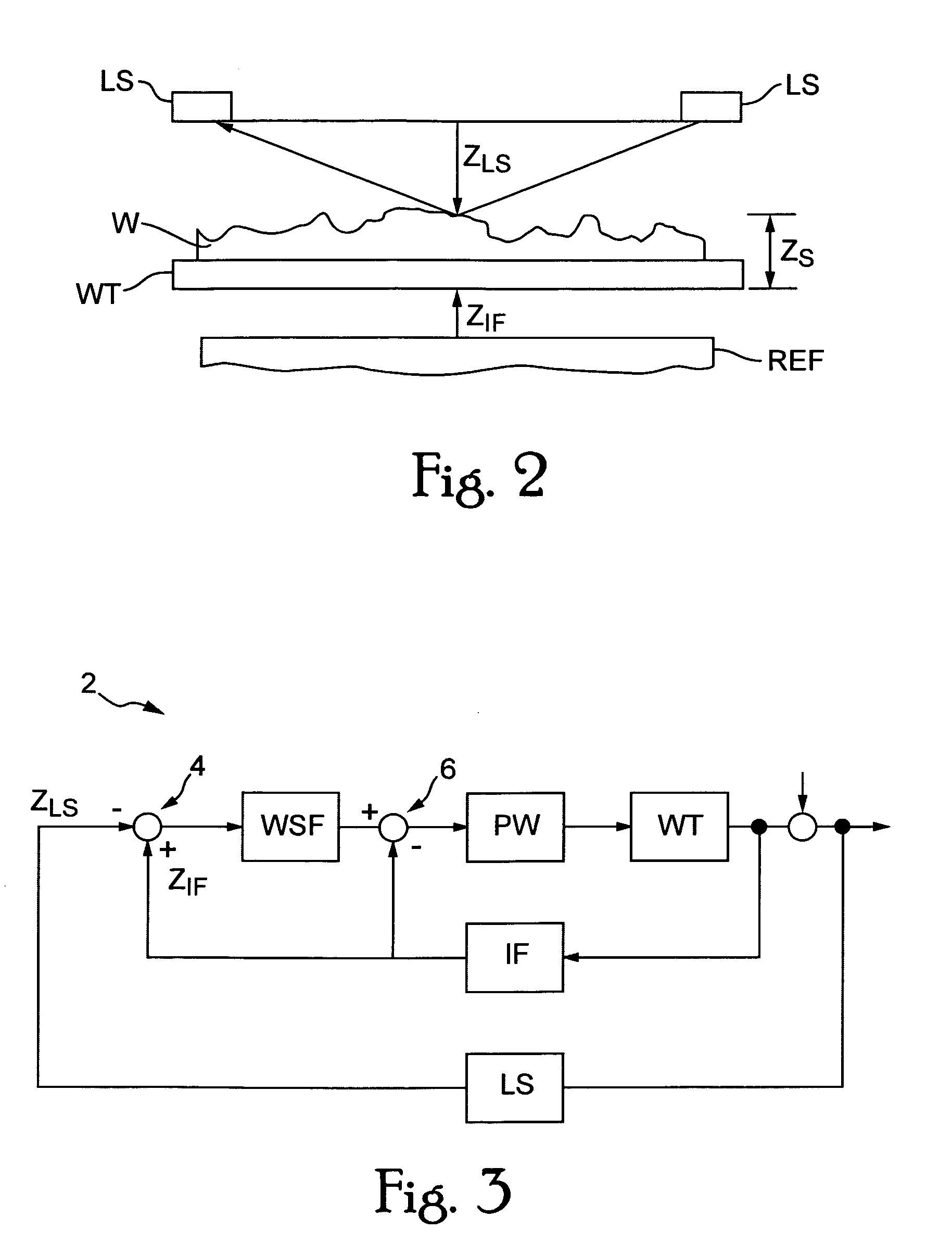
[0056] The single-stage substrate stepper, discussed directly hereinafter, has a servo unit that operates only on the basis of a feedback set-point signal, herewith the leveling takes place “on-the-fly”. During exposure of the substrate, the substrate height (distance of the surface of the substrate with respect to a reference frame REF) is determined on one location point and fed back to the servo unit. For this determination a measurement is performed by a level sensor LS yielding the distance of the substrate (wafer) surface with respect to a fixed point on the substrate table WT.

[0057] For example, as shown in FIG. 2, the combined height of the substrate (also called wafer) W and the substrate table WT (on which the substrate W is fixed) is defined as Zs. Now, if the position of the substrate table WT is measured by an interferometer IF with respect to the reference frame REF as shown in FIG. 2 and indicated by ZIF, the relation ZS=ZLS−ZIF holds, and the orientation of the surf...


PUM


Abstract

The present invention discloses a lithographic apparatus a lithographic apparatus with an improved focus control system. The lithographic apparatus includes an illumination system configured to provide a beam of radiation, a first support structure configured to support a patterning device that imparts the beam of radiation with a desired pattern in its cross-section, a second support structure that includes a substrate holder for holding a substrate, a projection system configured to project the patterned beam of radiation onto a target portion on a surface of the substrate, and a servo unit configured to position the substrate holder. The apparatus further includes a sensor unit configured to determine a distance of at least one location point on the surface of the substrate relative to a reference plane, a memory unit configured to store surface information of the substrate based on respective distances of corresponding the at least one location point on the substrate surface, and a calculating unit configured to determine a feed-forward set-point signal based on the stored surface information, such that the feed-forward set-point signal is forwardly fed to the servo unit in order to position the substrate holder.

Description

BACKGROUND OF THE INVENTION [0001] 1. Field of the Invention [0002] The present invention relates to lithographic apparatus with improved focus control. [0003] 2. Description of the Related Art [0004] Lithographic apparatus can be used, for example, in the manufacture of integrated circuits (ICs). In such a case, a patterning device may be used to generate a desired circuit pattern corresponding to an individual layer of the IC, and this pattern can be imaged onto a target portion (e.g. comprising one or more dies) on a substrate (silicon wafer) that has been coated with a layer of radiation-sensitive material (resist). [0005] Generally, such apparatus include an illumination system for supplying a projection beam of radiation, a support structure for supporting the patterning device, a substrate holder for holding a substrate, and a projection system for projecting the patterned beam onto a target portion of the substrate. More information with regard to lithographic devices as her...

Claims


Application Information

Patent Timeline
IPC IPC(8): H01L21/027G03F7/20G03F9/00
CPCG03F9/7003G03F9/7034G03F9/7015G07D2211/00G07F19/201
Inventor BUTLER, HANSBOONMAN, MARCUS EMILE JOANNESVAN DEN BIGGELAAR, PETRUS MARINUS CHRISTIANUS MARIA
Owner ASML NETHERLANDS BV
Why Eureka
Try Eureka