Method of optimizing an objective with fluoride crystal lenses, and objective with fluoride crystal lenses
- Summary
- Abstract
- Description
- Claims
- Application Information
AI Technical Summary
Benefits of technology
Problems solved by technology
Method used
Image
Examples
first embodiment
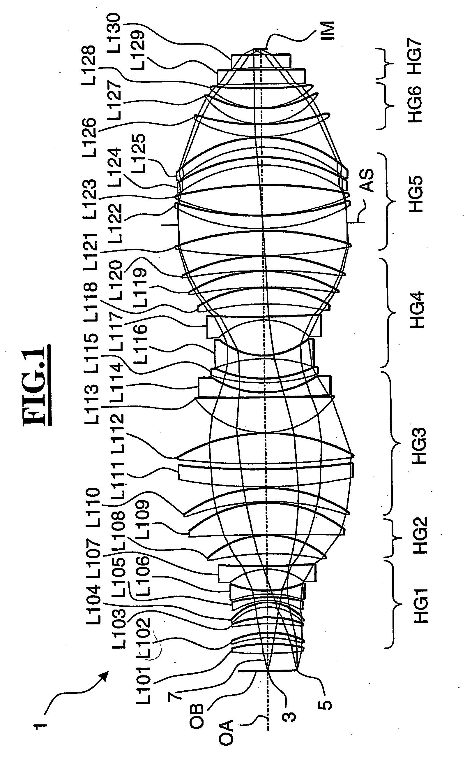
[0118]FIG. 1 represents in the form of a lens section an objective 1 whose optical data were determined by the numerical optimizing method in accordance with the invention. The objective 1 is a refractive projection objective for a microlithography projection system designed for the working wavelength of 157 nm. The optical data for this objective are listed in Table 1. The lenses L101 to L130 of this objective consist of calcium fluoride crystal. The image-side numerical aperture of the objective is 0.9. The object field, which is centered on the optical axis OA has a diameter of 92.4 mm. Located on the optical axis OA is the central object point 3, while the object point 5 is located at the border of the object field. The imaging scale factor of the objective 1 between the object plane OB and the image plane IM is 0.25. The imaging performance of the objective 1 is corrected to such a high degree that for all image points of the object field the mean deviation of the wave front fr...
third embodiment
[0197] In a third step of the optimizing process, angles of rotation γL are assigned to the fluoride crystal lenses of the first homogeneous group and the second homogeneous group. Given that in this third embodiment the lens axes of the barium fluoride lenses as well as of the calcium fluoride lenses are oriented in the crystallographic (111)-direction, the individual lenses are assigned an angle of rotation of either 0° or 60°. If the lens axes were pointing in the crystallographic (100)-direction, the angle to assign to the lenses would be either 0° or 45°.
[0198] In a fourth step of the optimizing method, the optical retardation ORLG=∑L701 to L730BFL
is calculated for the lenses L701 to L730. The calculation is based on an outer aperture ray 707.
[0199] In a fifth step of the optimizing method, the respective asymmetries of the retardation ORASHGI=∑L in HGI(MAL·DIL·DSL·APL·SPL) andORASHGII=∑L in HGII(MAL·DIL·DSL·APL·SPL)
are calculated for the lenses of the fir...
fourth embodiment
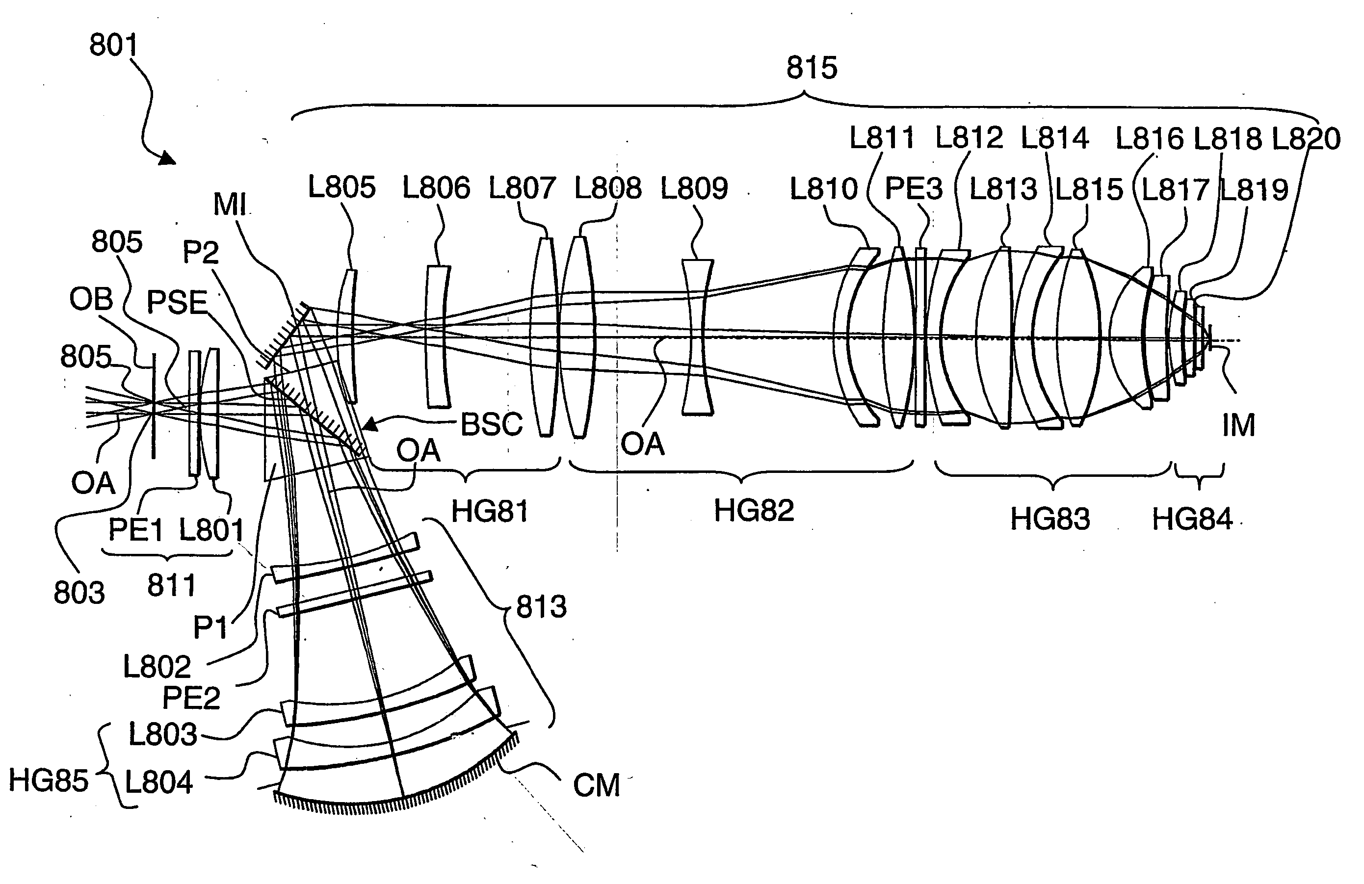
[0214]FIG. 8 illustrates a fourth embodiment in which the invention was put into practice in an objective 801. The objective 801 is a catadioptric projection objective for a microlithography projection system. The optical data for the objective 801 are listed in Table 10. The image-side numerical aperture of the objective 801 is 0.9. The object field which is centered on the optical axis OA has a diameter of 106.4 mm. The central object point 803 is located on the optical axis OA, and a further object point 805 is located at the periphery of the object field. The imaging scale ratio of the objective 801 between the object plane OB and the image plane IM is 0.25. The imaging performance of the objective 801 is corrected to such a high degree that the deviation from the wave front of an ideal spherical wave for all object points of the object field is less than six thousandths of a wavelength in relation to a working wavelength of 157 nm, if only those aberrations are considered that ...
PUM
 Abstract
Description
Claims
Application Information
 - R&D
- Intellectual Property
- Life Sciences
- Materials
- Tech Scout
- Unparalleled Data Quality
- Higher Quality Content
- 60% Fewer Hallucinations
Browse by: Latest US Patents, China's latest patents, Technical Efficacy Thesaurus, Application Domain, Technology Topic, Popular Technical Reports.
© 2025 PatSnap. All rights reserved.Legal|Privacy policy|Modern Slavery Act Transparency Statement|Sitemap|About US| Contact US: help@patsnap.com


