Frequency-current conversion circuit, equalizer, and optical disc apparatus

a technology of applied in the field of frequency-current conversion circuit, equalizer and optical disc apparatus, can solve problems such as difficulties in the potential of node d, and achieve the effect of stabilizing the frequency characteristic and reducing the errors of digital data

Inactive Publication Date: 2005-08-18
ROHM CO LTD
View PDF7 Cites 2 Cited by
  • Summary
  • Abstract
  • Description
  • Claims
  • Application Information

AI Technical Summary

Benefits of technology

[0021] The frequency-current conversion circuit of various preferred embodiments of the present invention is able to obtain a output current which has no ripple by providing a sample and hold circuit that samples and holds the output voltage of the charging / discharging circuit within a predetermined period during which the first capacitor is forcibly discharged between the charging / discharging circuit and the voltage-current conversion circuit, whereby a contribution can be made to stabilization of the frequency characteristic of the equalizer that is used in a high-speed optical disc apparatus. Further, by providing and uniquely arranging the frequency-current conversion circuit, the equalizer of preferred embodiments of the present invention is able to stabilize the frequency characteristic even in a high-speed operation. Further, through the provision and unique operation of the equalizer, the optical disc apparatus of a preferred embodiment of the present invention is able to reduce errors in the digital data that is demodulated even in a high-speed operation.

Problems solved by technology

However, when the speed of the optical disc is changed, it is difficult for the potential of node D to track the change in the frequency of the input clock with the appropriate timing.

Method used


Image

  • Frequency-current conversion circuit, equalizer, and optical disc apparatus
  • Frequency-current conversion circuit, equalizer, and optical disc apparatus
  • Frequency-current conversion circuit, equalizer, and optical disc apparatus

Examples


Embodiment Construction

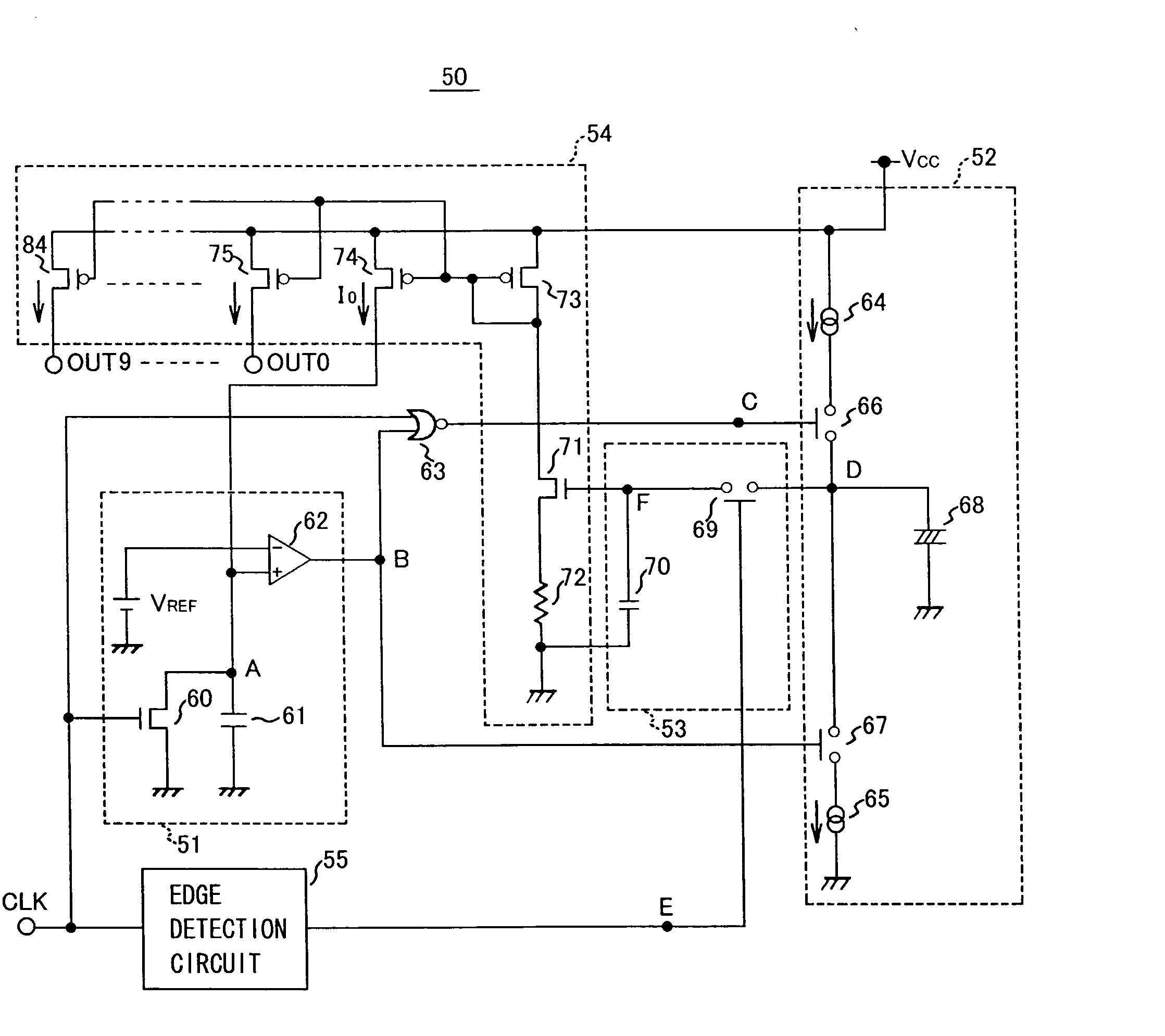
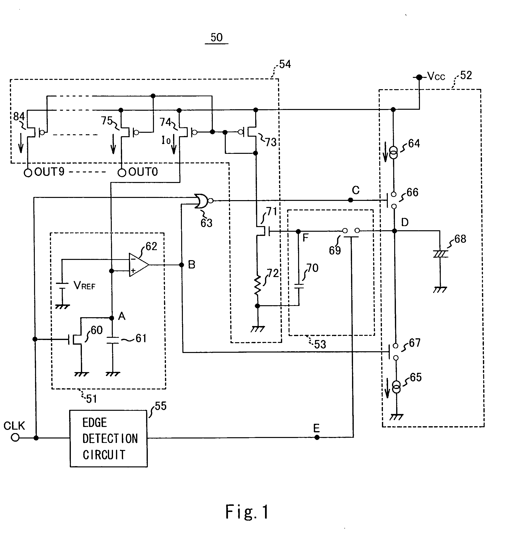
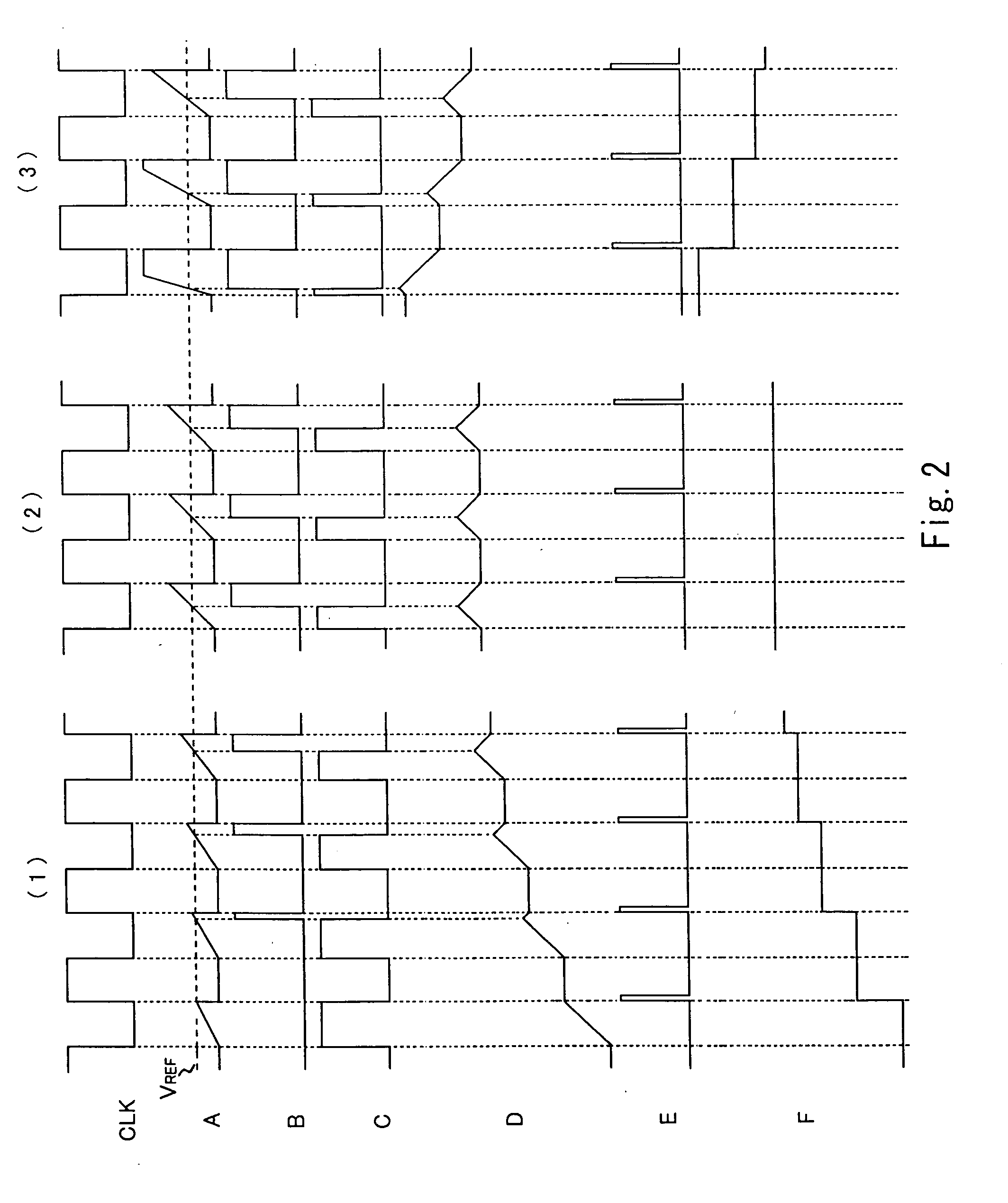
[0030] A frequency-current conversion circuit of a preferred embodiment of the present invention will be described hereinbelow. FIG. 1 is a circuit diagram of a frequency-current conversion circuit 50. FIG. 2 is a waveform diagram that shows waveforms for the voltage at the respective nodes of the frequency-current conversion circuit 50, that is, the input clock of the input clock terminal CLK and nodes A to F (described later), wherein portions (1), (2), (3) show cases where the output reference current Io of transistor 74 (described subsequently) has three different sizes. The frequency-current conversion circuit 50 generates an output current corresponding with the frequency of the input clock. The frequency-current conversion circuit 50 includes a comparison circuit 51, a charging / discharging circuit 52, a sample and hold circuit 53, a voltage-current conversion circuit 54 and an edge detection circuit 55. The comparison circuit 51 includes a first capacitor 61 that is charged b...


PUM

PropertyMeasurementUnit
frequencyaaaaaaaaaa
voltageaaaaaaaaaa
output voltageaaaaaaaaaa

Abstract

A frequency-current conversion circuit permits stabilization of the frequency characteristic of an equalizer that is used in a high-speed optical disc apparatus. The frequency-current conversion circuit includes a comparison circuit that includes a first capacitor that is charged by an output reference current and is forcibly discharged over a predetermined period from the change point of the input clock of the input clock terminal, and that compares the voltage produced in the first capacitor with a reference voltage, a charging/discharging circuit that includes a second capacitor that is charged and discharged in accordance with the output of the comparison circuit and that outputs a voltage that is produced in the second capacitor, a sample and hold circuit that samples and holds the output voltage of the charging/discharging circuit within the predetermined period, and a voltage-current conversion circuit that converts the held voltage to the output reference current and an output current that is proportional to the output reference current.

Description

BACKGROUND OF THE INVENTION [0001] 1. Field of the Invention [0002] The present invention relates to a frequency-current conversion circuit that generates an output current that corresponds with the frequency of an input clock, an equalizer including the frequency-current conversion circuit and having a steep frequency characteristic, and an optical disc apparatus that includes the equalizer. [0003] 2. Description of the Related Art [0004] An optical disc apparatus has the basic structure of the signal processing blocks shown in FIG. 3. That is, an optical disc apparatus 1 detects an optical signal according to pits in an optical disc 9 such as a compact disc (CD) or digital versatile disc (DVD) by means of a photodetector 10, amplifies the detected signal by means of an RF amplifier 11, and corrects the signal (differential RF signal) by means of an equalizer 12. The optical disc apparatus 1 then binarizes the corrected signal by means of a slicer 13, and demodulates (reproduces) d...

Claims


Application Information

Patent Timeline
Patent Type & Authority Applications(United States)
IPC IPC(8): G11B7/00G01R23/06G11B20/10H02H7/00
CPCG11B20/10009G11B20/10222G11B20/10046B65B1/24B65B65/02
Inventor HAMAGUCHI, TSUYOSHI
Owner ROHM CO LTD
Why Eureka
Try Eureka