Self-excited vibration heat pipe and computer with the heat pipe

a heat pipe and self-excitation technology, applied in the field of self-excited oscillation heat pipes, can solve the problems of increasing price and trouble, rendering the capillary structure complex, and difficult to provide the capillary structure on the inner surface of the bellows, etc., to achieve low price and trouble, and high heat transfer performance. , the effect of easy manufacturing

Inactive Publication Date: 2005-08-18
MIYAZAKI YOSHIRO +1
View PDF8 Cites 35 Cited by
  • Summary
  • Abstract
  • Description
  • Claims
  • Application Information

AI Technical Summary

Benefits of technology

[0040] Since the configuration becomes simpler compared with the other systems by use of the self-excited oscillation heat pipe, it becomes lightweight and has less trouble and can be manufactured with ease. Further, since the working fluid directly reciprocates between the main unit and the radiation surface to transfer heat, it has properties capable of high heat transfer performance compared with a radiation unit in which two heat pipes can be connected to each other via a slide contact type heat exchanger having a hinge function.
[0041] Further, since the radiation unit employing the self-excited oscillation heat pipe operates passively without using a power generated by a pump and so forth, it has features having no increase in power compared with a radiation unit employing a fluid loop in which cooling water is circulated by use of the pump. Accordingly, it is possible to provide the radiation unit employing the self-excited oscillation heat pipe which does not requires a power for operation thereof, and is lightweight and high in tra

Problems solved by technology

However, it is technically very difficult to provide the capillary structure on an inner surface of the bellows.
However, if the bellows is provided on the conduit, the capillary structure which has been conventionally provided on the inner wall of the pipe is needed to be provided remote from the inner wall of the pipe, rendering the capillary structure complex.
Accordingly, there arises a problem that the heat pipe is difficult to be rendered compact and lightweight associated with rendering in a small pipe, leading to the increase in price and trouble.
However, since the evaporation pipe of the capillary pumped loop or that of the loop heat pipe has a complex capillary structure and fluid channel to require high precision in manufacturing and assembling thereof, resulting in very expensive, and hence it is limited to a special purpose such as a heat control in a spacecraft.
Further, there is a technical problem of the possibility of occurrence of trouble in starting or re-priming.
Further, there is a problem that the evaporation pipe is difficult to be rendered in a small pipe and it is heavy in weight and large in volume.
There is a restriction in the closed two-phase thermo-siphon of the loop type that a cooling portion has to be installed at a position higher than a heating portion, and a head to be obtained associated with rendering compact becomes small, causing a problem of the reduction of heat transfer performance.
A method of connecting two single heat pipes by a sliding contact type heat exchanger having a hinge function or a flexible good heat conductor has a problem that thermal resistance in each heat pipe is added and thermal resistance is added at the connection portion, thereby lowering a heat transfer performance compared with the single heat pipe.
Further, there is a problem of leading

Method used


Image

  • Self-excited vibration heat pipe and computer with the heat pipe
  • Self-excited vibration heat pipe and computer with the heat pipe
  • Self-excited vibration heat pipe and computer with the heat pipe

Examples


Embodiment Construction

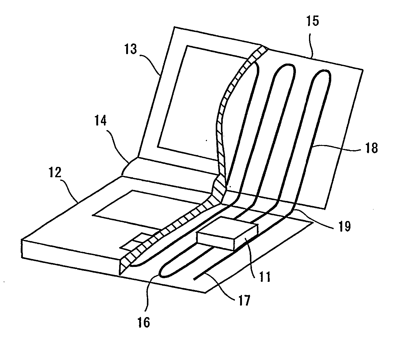
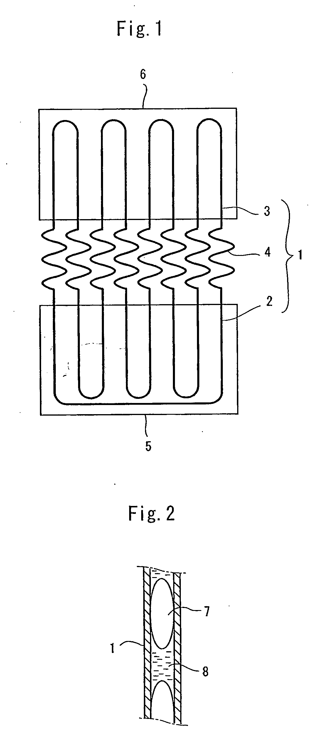
[0052] In FIG. 1, a conduit 1 of a self-excited oscillation heat pipe comprises a conduit part 2, a conduit part 3, and a conduit part 4, wherein the conduit part 2 is disposed on a heating part 5, the conduit part 3 is disposed on the cooling part cooling part 6, the conduit part 2 and the conduit part 3 are connected each other by the conduit part 4, and the conduit 1 is disposed to reciprocate multiple times between the heating part 5 and the cooling part 6.

[0053] The conduit part 4 is formed by bending the conduit in a waved bent shape to have flexibility, and hence the heating part 5 and the cooling part 6 can be foldable.

[0054] A working fluid vapor 7 and a working fluid liquid 8 are distributed inside the conduit 1 of the self-excited oscillation heat pipe as shown in FIG. 2, whereby heat transfer from the heating part 5 to the cooling part 6 is effected by reciprocation of the working fluid vapor 7 and the working fluid liquid 8 between the heating part 5 and the cooling p...


PUM


Abstract

The present invention is to provide a heat pipe which is high in heat transfer performance and reliability and can be low priced, compact and lightweight, and has flexibility, and a computer provided with the heat pipe. At least a part of a conduit (1) constituting a container of a self-excited oscillation heat pipe is formed in a shape having flexibility such as a waved bent shape. Alternatively, at least a part of the container of the self-excited oscillation heat pipe is formed of a material having flexibility such as super elastic alloys.

Description

TECHNICAL FIELD [0001] The present invention relates to a self-excited oscillation heat pipe having flexibility and a computer provided with the self-excited oscillation heat pipe. BACKGROUND TECHNOLOGY [0002] As a heat pipe which has been put into practice so far, there are typically three examples, namely, a wick type heat type, an closed two-phase thermo-siphon and a self-excited oscillation heat pipe. As a structure of a fluid channel, there are a single pipe type in which both ends of the fluid channel are closed and a loop type in which both ends of the fluid channel are connected to each other. [0003] In the case of installing such a heat pipe to a movable portion of a unit, the heat pipe is needed to be flexible. With the wick type heat pipe and the closed two-phase thermo-siphon, it is proposed to provide bellows at a part of fluid channel constituting a container in order to obtain a heat pipe having flexibility With the single pipe type of the wick type heat pipe and the ...

Claims


Application Information

Patent Timeline
IPC IPC(8): F28D15/02G06F1/20
CPCF28D15/0241F28D15/0266G06F2200/203G06F2200/201G06F1/203
Inventor MIYAZAKI, YOSHIROMIYAZAKI, KANEKO
Owner MIYAZAKI YOSHIRO
Why Eureka
Try Eureka