Gps-based underwater cable positioning system

a positioning system and underwater cable technology, applied in direction finders using ultrasonic/sonic/infrasonic waves, instruments, etc., can solve the problems of shortening the battery life of battery-powered devices, affecting the positioning geometry of acoustic ranging transceivers, and affecting the accuracy of gps-based cable positioning, etc., to achieve the effect of improving the positioning geometry

Active Publication Date: 2005-08-18
INPUT OUTPUT INC
View PDF2 Cites 133 Cited by
  • Summary
  • Abstract
  • Description
  • Claims
  • Application Information

AI Technical Summary

Benefits of technology

[0008] In another version of the positioning system, an acoustic transceiver unit is attached to one of the cables. The acoustic transceiver unit includes an acoustic receiver and an acoustic transmitter. The acoustic receiver receives the acoustic message signals transmitted by the surface units and determines its own position from those acoustic message signals. The acoustic transmitter in the acoustic transceiver unit transmits into the water ...

Problems solved by technology

For example, the acoustic ranging transceivers take a lot of power to transmit acoustic pulses of sufficient energy to achieve quality long ranges.
This power requirement shortens battery life for battery-powered devices and puts constraints on those devices powered inductively from the streamers.
Furthermore, in-line ranges (i.e., ranges along the length of the streamer) are difficult to achieve especially if the acoustic transducers are mounted within, rather than suspended from, the streamers.
And in-streamer compasses are negatively affected by their proximity to metal str...

Method used


Image

  • Gps-based underwater cable positioning system
  • Gps-based underwater cable positioning system
  • Gps-based underwater cable positioning system

Examples


Embodiment Construction

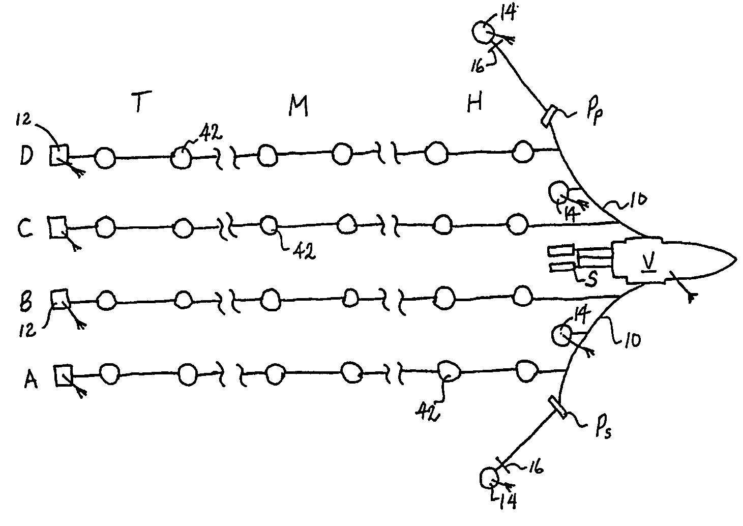
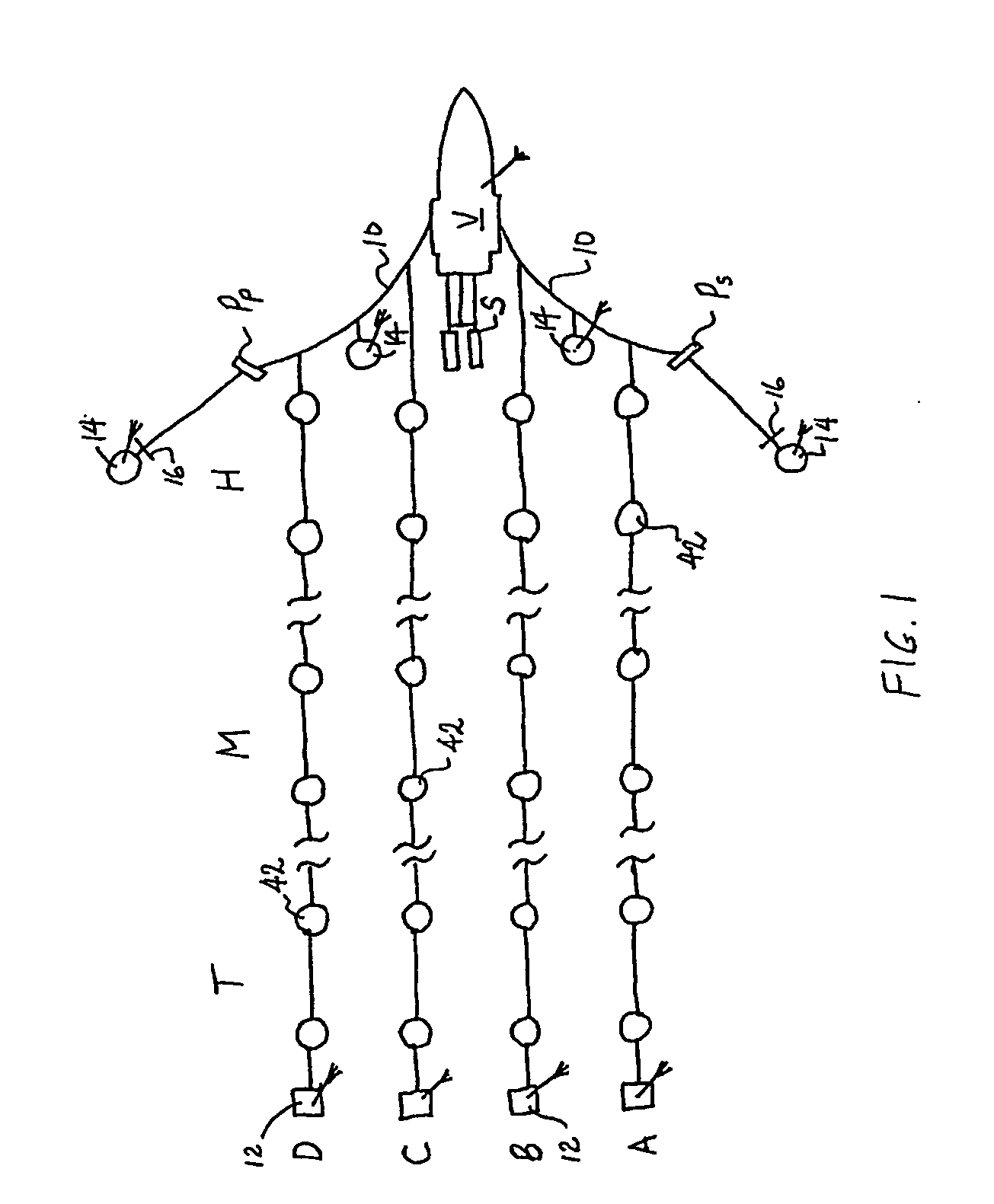
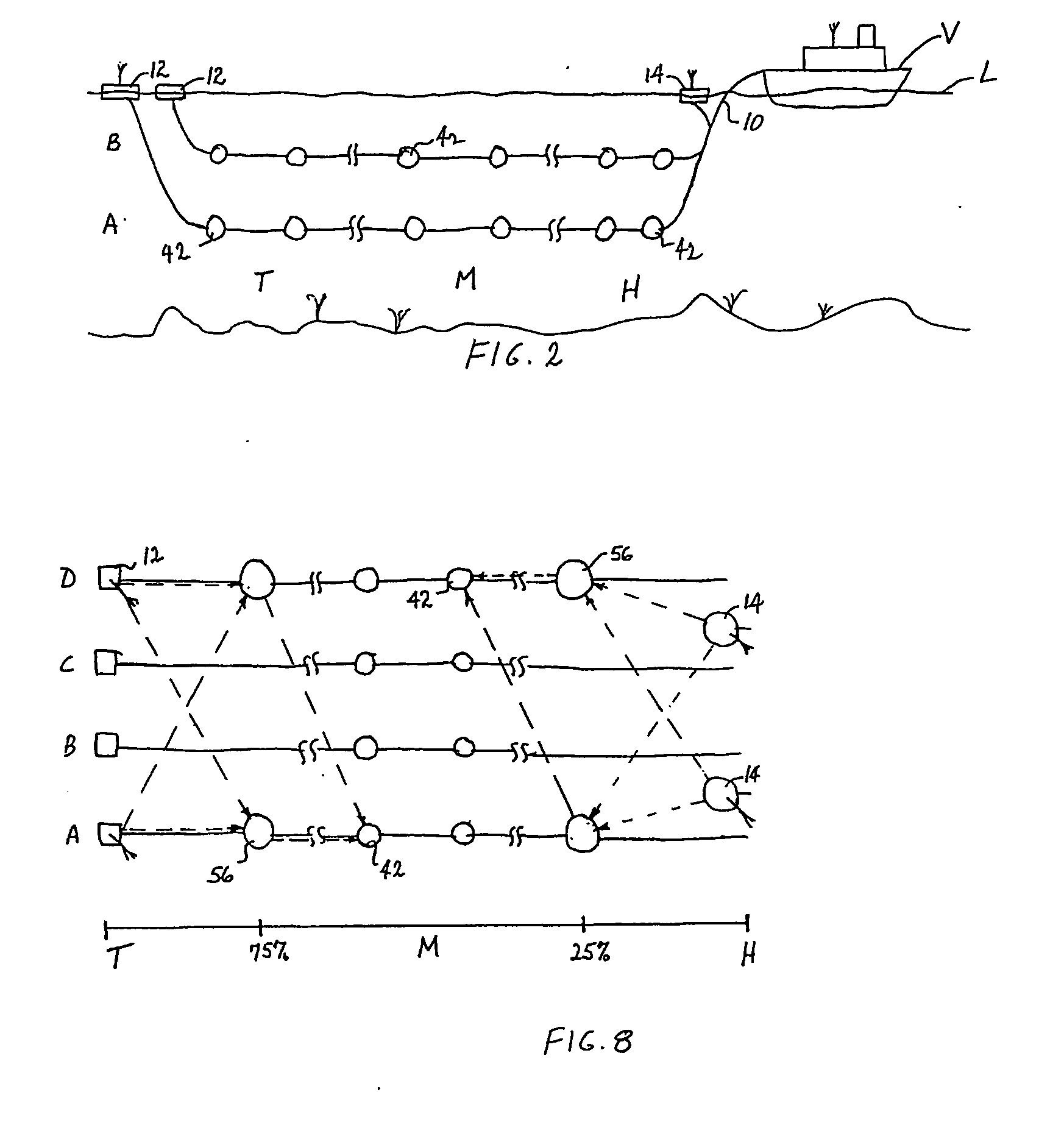
[0022] A streamer positioning system embodying features of the invention is depicted in the example of FIGS. 1 and 2. In the example, a marine vessel V is towing a network of hydrophone streamers, represented in FIG. 1 as four streamers A, B, C, and D. Of course, more or fewer streamers could be used. Streamers used in seismic prospecting are typically a few kilometers long. For example, the streamers may be 8 km long with the outermost streamers 700 m apart from each other. Here the streamers are shown broken into a head end section H nearest the vessel, a middle section M, and a tail end section T. In this example, streamer A is the outer starboard streamer; streamer B is the inner starboard streamer; streamer C is the inner port streamer; and streamer D is the outer port streamer. In FIG. 2, only the starboard streamers A, B are depicted at different depths for clarity. Depth control devices (not shown) attached to the streamers about every 150 meters maintain the cables at a con...


PUM


Abstract

A GPS-based underwater cable positioning system for use in determining the shape and position of hydrophone streamers towed underwater behind survey vessels involved in marine seismic prospecting. The system includes a plurality of surface units towed behind the vessel. Each surface unit includes a GPS receiver to receive radio frequency GPS signals and to determine its positions. Each surface unit also has an acoustic transmitter to transmit an acoustic message signal representing its position and an optional time stamp into the water. Acoustic receiver units, attached spaced apart locations along one or more streamer cables, each include an acoustic receiver to receive the acoustic message signals from the surface units and to determine its position from the message signals. To augment the message signals from the surface units at locations distant from the surface units, acoustic transceiver units may be used. The acoustic transceiver units are attached to the streamer cables at ranges between the surface units and distant acoustic receiver units. The acoustic transceiver units each include an acoustic receiver that performs as the receivers in the acoustic receiver units and an acoustic transmitter to transmit acoustic message signals representing its position and an optional time stamp into the water to be received by the acoustic receiver units. In this way, the positions and shapes of towed streamer cables can be determined.

Description

BACKGROUND [0001] The invention relates generally to offshore seismic prospecting and, more particularly, to apparatus and methods for determining the position and shape of hydrophone streamer or bottom cables towed or dragged underwater behind seismic survey vessels. [0002] In offshore seismic prospecting, a group of underwater cables, commonly referred to as streamers, is towed through the water by a marine vessel, such as a surface ship. Each streamer is instrumented with an array of hydrophones used to receive seismic reflections off undersea geologic formations and with a variety of sensors and control devices used to determine the shape and position of the streamers and to control their depth. The surface ship also tows a seismic source, typically an array of air guns fired at regular intervals to radiate seismic energy into the geologic formations. For an accurate survey, the shape and position of the streamers and the seismic source must be known accurately. Conventionally, ...

Claims


Application Information

Patent Timeline
IPC IPC(8): G01S1/72G01S5/00G01S5/14G01S5/26G01S5/30G01S7/00G01S19/42G01V1/38G01V1/40
CPCG01S1/72G01S5/0072G01S5/26G01V1/3835G01S7/003G01S19/42G01S5/30Y02A90/30
Inventor LAMBERT, DALE JROUQUETTE, ROBERT E.SEALE, DANIEL B.GUILLOT, CLEM B.
Owner INPUT OUTPUT INC
Why Eureka
Try Eureka