Power amplifier arrangement having an antenna, and a method for amplification and emission of a signal

a technology of power amplifier and antenna, which is applied in the direction of gated amplifier, baseband system details, gain control, etc., can solve the problems of not inconsiderable power loss, the complex transformation of the impedance of the active power amplifier to the antenna impedance is becoming ever greater, etc., and achieves better efficiency, higher output impedance, and better efficiency

Active Publication Date: 2005-08-18
APPLE INC
View PDF10 Cites 15 Cited by
  • Summary
  • Abstract
  • Description
  • Claims
  • Application Information

AI Technical Summary

Benefits of technology

[0014] A bandwidth of, for example, 800 MHz to 2500 MHz can be achieved without any problems on the basis of the present invention.
[0015] The individual amplifiers may have a considerably higher output impedance than a single power amplifier. Skilful design of the individual antennas allows the losses which occur as a result of any matching network that may be present to be reduced considerably. It may even be possible to dispense completely with a matching network, depending on the design of the amplifiers and of the antennas.
[0016] In another embodiment of the invention, the maximum power to be emitted from the power ampl...

Problems solved by technology

The increasing number of frequency bands means that the complexity of the impedance transformation from the impedance of the active p...

Method used


Image

  • Power amplifier arrangement having an antenna, and a method for amplification and emission of a signal
  • Power amplifier arrangement having an antenna, and a method for amplification and emission of a signal
  • Power amplifier arrangement having an antenna, and a method for amplification and emission of a signal

Examples


Embodiment Construction

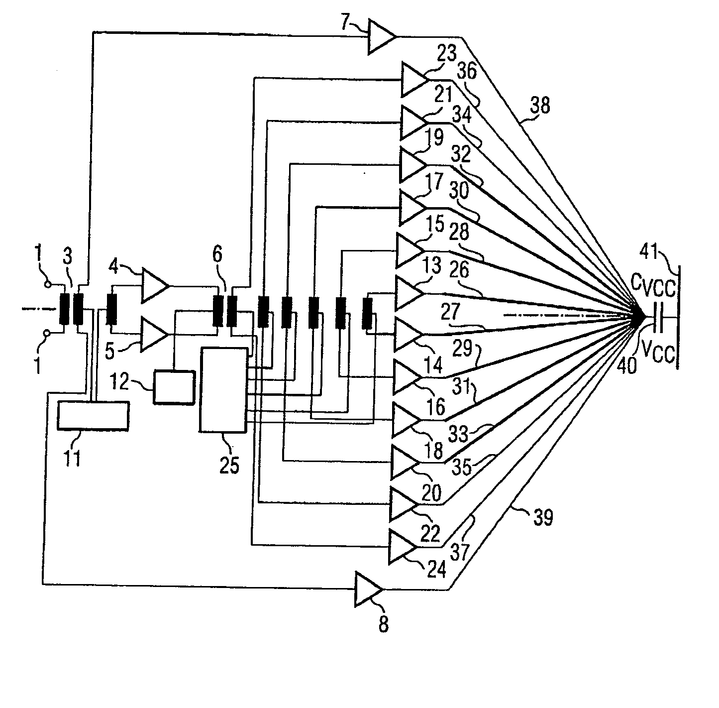
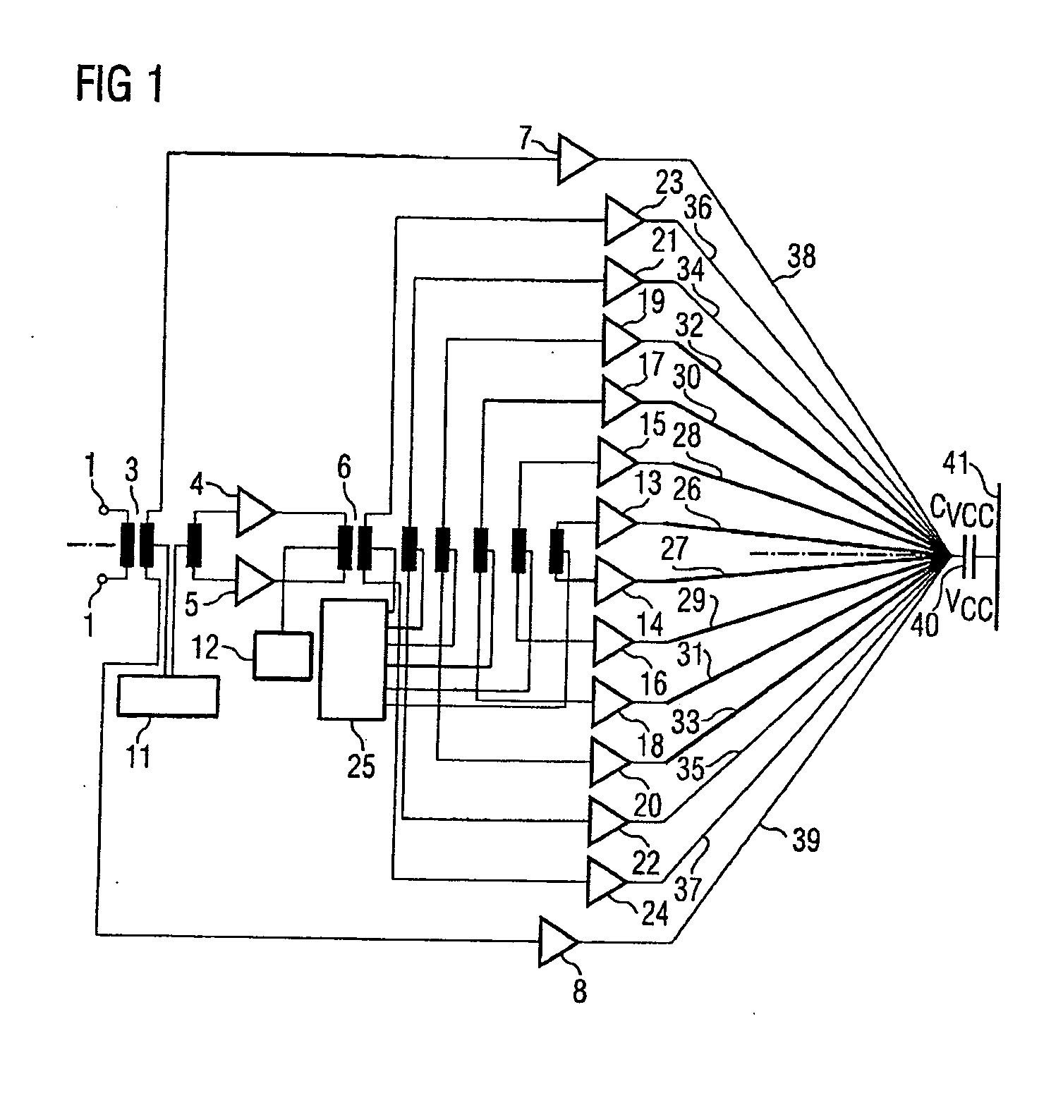
[0039]FIG. 1 shows a power amplifier arrangement having an input 1, which is balanced and is designed to carry difference signals. The primary of a radio-frequency transformer 3 is connected to the input 1. The secondary of the transformer 3 is connected via a respective input stage 4, 5 to the primary of a further radio-frequency transformer 6. The secondary of the transformer 3 is also connected to the input of a respective bypass amplifier 7, 8. A center tap on each of the two secondary windings of the transformer 3 is connected to a control block 11. A center tap on the primary of the transformer 6 is connected to a further control block 12.

[0040] A total of six secondary windings are provided on the secondary of the radio-frequency transformer 6, each having two connections to, in each case, one input of an amplifier 13 to 24. The amplifiers 13 to 24 are in this case each associated with one another in pairs. The six secondary windings of the transformer 6 are also connected v...


PUM


Abstract

A power amplifier arrangement having a distributed antenna is disclosed. The power amplifier arrangement has two or more signal paths which are coupled to a common input. Each signal path has an amplifier with a downstream antenna. The respective signal paths with the antenna are activated or deactivated by a control device as a function of the desired gain or output power. This results in high efficiency over a wide frequency range. The polar diagrams of the antenna branches preferably correspond to those of a single antenna.

Description

REFERENCE TO RELATED APPLICATIONS [0001] This application claims the benefit of the priority date of German application DE 102004001236.9, filed on Jan. 7, 2004, the contents of which are herein incorporated by reference in their entirety. FIELD OF THE INVENTION [0002] The present invention relates to a power amplifier arrangement having an antenna, to use of the power amplifier arrangement in a radio transmission arrangement, and in a mobile radio, and to a method for amplification and emission of a signal. BACKGROUND OF THE INVENTION [0003] Power amplifier arrangements having an antenna are used, for example, in the transmission paths of mobile radios. Mobile radios are subject to an increasing requirement for a wider bandwidth in the radio-frequency signal processing. For example, mobile radios based on the GSM standard (Global System for Mobile Communication) nowadays normally already have three transmission and reception bands. Appliances such as these are also referred to as t...

Claims


Application Information

Patent Timeline
IPC IPC(8): H01Q11/12H03F1/02H03F3/19H03F3/21H03F3/60H03F3/72H03G1/00H03G3/30H04B1/00H04B1/04H04B1/40
CPCH01Q1/36H01Q3/28H03F1/0277H03F3/19H03F3/211H03F3/602H04B2001/045H03F2200/537H03G1/0088H03G3/3042H04B1/0483H04B2001/0416H03F3/72H03F1/02H03F3/24
Inventor FENK, JOSEF
Owner APPLE INC
Why Eureka
Try Eureka