Laser shock peening of medical devices

a technology of medical devices and shock peening, which is applied in the field of medical devices, can solve the problems of reducing the performance of the device, affecting the quality of the device, and the effectiveness of such processes is typically limited, and achieves the effects of less disruption to the bloodstream, increased flexibility and strength, and reduced device performan

Inactive Publication Date: 2005-08-18
BOSTON SCI SCIMED INC
View PDF35 Cites 75 Cited by
  • Summary
  • Abstract
  • Description
  • Claims
  • Application Information

AI Technical Summary

Benefits of technology

[0005] The present invention pertains to laser shock peening of medical devices. An illustrative laser shock peening process in accordance with an embodiment of the present invention includes the steps of providing a workpiece having a target surface to be irradiated, applying an absorption overlay onto the target surface, and directing a laser beam onto the absorption overlay to induce a pressure shock wave within the workpiece that can be used to produce one or more compressive residual stress regions therein. A high-energy laser apparatus capable of producing one or more intense laser beams may be provided to vaporize the absorption overlay material and form an interface layer of plasma above the target surface. The rapid expansion of volume and pressure at the interface layer induces a pressure shock wave within the workpiece that is greater than the dynamic yield stress of the workpiece material, creating a compressive residual stress region within the workpiece. In certain embodiments, a confining medium such as water can be provided to increase the magnitude of the induced pressure shock wave, further increasing the depth of the compressive residual stress region within the workpiece.
[0008] Using one or more of the aforesaid processes, a medical device such as a stent, guidewire, intravascular filter, guide catheter, needle, needle stylet, etc. may be formed having one or more compressive residual stress regions therein. In one illustrative embodiment, for example, a stent having a number of struts may include one or more compressive residual stress regions formed therein. In use, the compressive residual stress regions increase the flexibility and fatigue strength of the material at these locations, allowing the use of thinner struts with less disruption to the bloodstream. In another illustrative embodiment, a guidewire may include a core wire with one or more compressive residual stress regions formed in a pattern along the length of the guidewire, or within the entire guidewire. In certain embodiments, the one or more compressive residual stress regions may be formed about a joint used to fuse various components of the guidewire together. In use, the compressive residual stress regions can be used to impart one or more desired characteristics to the guidewire such as increased flexibility and strength.

Problems solved by technology

Repeated expansion and contraction of the device within the body may accelerate the growth of these cracks, reducing the performance of the device over time.
While conventional processes such as shot peening have been used in treating medical devices, the efficacy of such processes are typically limited by the depth, and in some cases the accuracy, at which the compressive residual stress regions can be formed within the workpiece.
Since many convention processes such as shot peening are limited by the depth at which the compressive residual stress region can be formed, such processes are not always effective at preventing cracks in highly flexible regions deep within the surface of the workpiece.

Method used


Image

  • Laser shock peening of medical devices
  • Laser shock peening of medical devices
  • Laser shock peening of medical devices

Examples


Embodiment Construction

[0029] The following description should be read with reference to the drawings, in which like elements in different drawings are numbered in like fashion. The drawings, which are not necessarily to scale, depict selected embodiments and are not intended to limit the scope of the invention. Although examples of construction, dimensions, and materials are illustrated for the various elements, those skilled in the art will recognize that many of the examples provided have suitable alternatives that may be utilized.

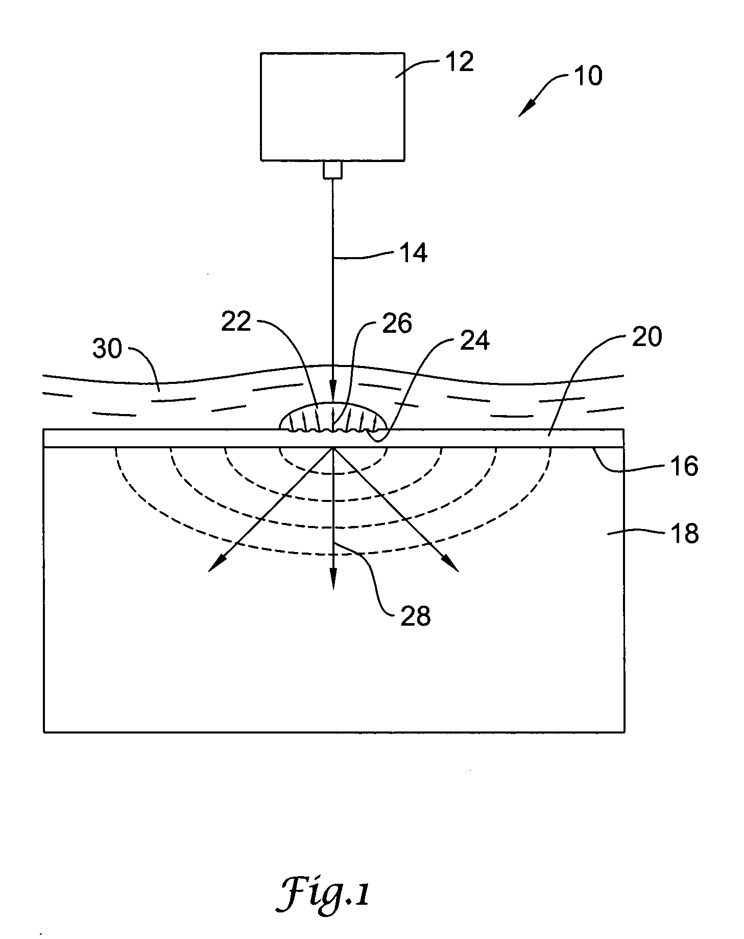
[0030]FIG. 1 is a diagrammatic view showing an illustrative laser shock peening process for use in producing a compressive residual stress region within a workpiece. The laser shock peening process, represented generally by reference number 10, includes a high-energy laser apparatus 12 configured to direct an intense laser beam 14 onto the target surface 16 of a metallic workpiece 18. The workpiece 18 may comprise one or more components of a stent, guidewire, catheter, intra...


PUM

PropertyMeasurementUnit
pressureaaaaaaaaaa
pressureaaaaaaaaaa
compressive residual stressaaaaaaaaaa

Abstract

A laser shock peening process for producing one or more compressive residual stress regions in a medical device is disclosed. A high-energy laser apparatus can be utilized to direct an intense laser beam through a confining medium and onto the target surface of a workpiece. An absorption overlay disposed on the target surface of the workpiece absorbs the laser beam, inducing a pressure shock wave that forms a compressive residual stress region deep within the workpiece. Medical devices such as stents and guidewires having one or more of these compressive residual stress regions are also disclosed.

Description

FIELD OF THE INVENTION [0001] The present invention relates to medical devices and methods of manufacturing such devices. More specifically, the present invention pertains to laser shock peening of medical devices. BACKGROUND OF THE INVENTION [0002] Medical devices such as stents, guidewires, catheters, intravascular filters, needles, and needle stylets are used in performing a wide variety of medical procedures within the body. To permit such devices to be inserted into relatively small regions such as the cardiovascular and / or peripheral anatomies, the various components forming the device must be made relatively small while still maintaining a particular performance characteristic within the body such as high flexibility and fatigue strength. In the design of stents, for example, it is desirable to make the struts highly flexible to permit the stent to be easily collapsed and inserted into a deployment device such as a sheath or catheter. The stent must also be resistant to the f...

Claims


Application Information

Patent Timeline
Patent Type & Authority Applications(United States)
IPC IPC(8): A61F2/00A61F2/06A61F2/90C21D10/00
CPCA61F2/91C21D10/005A61F2250/0068
Inventor HOLMAN, THOMASWEBER, JAN
Owner BOSTON SCI SCIMED INC
Why Eureka
Try Eureka