MRI imageable medical device

a medical device and image technology, applied in the field of medical devices with imageable capabilities, can solve the problems of affecting the image affecting the treatment effect, and affecting the quality of the patient, so as to inhibit the distortion of the image of the medical resonance image taken

Inactive Publication Date: 2005-08-18
BIOPHAN TECH
View PDF0 Cites 85 Cited by
  • Summary
  • Abstract
  • Description
  • Claims
  • Application Information

AI Technical Summary

Benefits of technology

[0017] In accordance with this invention, there is provided a medical device comprised of a coating that inhibits distortion of medical resonance images taken of the device. When the device is exposed to radio frequency electromagnetic radiation with a frequency of from 10 megahertz to about 200 megahertz, at least 90 percent of such radio frequency electromagnetic radiation penetrates to the lumen of the device; and the concentration of the radio frequency electromagnetic radiation that penetrates to the lumen of the device is substantially identical at different points within such interior. The coating is comprised of magnetic material with an average particle size of less than about 40 nanometers.

Problems solved by technology

However, various stent designs substantially distort the surrounding of the stent during a Magnetic Resonance Imaging procedure” (see paragraph 0002).
Although coronary magnetic resonance angiography (MRA) has been successfully implemented for visualization of the native proximal and middle portions of the coronary artery tree, the in-stent lumen cannot now be visualized because of susceptibility artifacts and radiofrequency shielding, resulting in a local signal void.”
Furthermore, the stent Faraday Cage likely impedes the escape of whatever signal is generated in the lumen.
The stent's high magnetic susceptibility, however, perturbs the magnetic field in the vicinity of the implant.
This alters the resonance condition of protons in the vicinity, thus leading to intravoxel dephasing with an attendant loss of signal.
The net result with current metallic stents, most of which are stainless steel, is a signal void in the MRI images.
It is this structure that creates a Faraday Cage, and its associated problems with MRI.
But a current considerable factor weighing against the use of magnetic resonance imaging techniques to visualize implanted stents composed of ferromagnetic or electrically conductive materials is the inhibiting effect of such materials.
These materials cause sufficient distortion of the magnetic resonance field to preclude imaging the interior of the stent.
However, the Melzer solution lacks a suitable integration of an LC circuit within the stent.” The Alt patent does not specify in what respect(s) the “ .
. . Melzer solution lacks a suitable integration of an LC circuit within the stent.”
Unfortunately, most metal stents, particularly of stainless steel, obliterate MRI images of the anatomy in their vicinity and obscure the stent lumen in the image.
This solution is limited by the need for stents to have adequate radial strength and scaffolding.”
However, stents made form materials such as these would require larger strut dimensions to maintain adequate stent mechanical performance as compared to stents made out of metals.”
The problem with the prior art stents that have “adequate stent mechanical performance” is that magnetic resonance imaging is generally not able to view areas within such stents with adequate degrees of resolution.
However, various current stent designs prevent adequate imaging of the area surrounding the stent.
Instead, the images are distorted and thus cannot be used.”
First of all, the permanent influence of the surrounding magnetic field by stents containing ferromagnetic materials prevents adequate imaging.
However, stents made from materials such as these would require larger strut dimensions to maintain adequate stent mechanical performance as compared to stents made of metals.”
In spite of all of the research reflected in the prior art, none of the prior art designs has provided a metallic stent that, when subjected to MRI imaging, provides adequate resolution of objects disposed within the stent.

Method used


Image

  • MRI imageable medical device
  • MRI imageable medical device
  • MRI imageable medical device

Examples


Embodiment Construction

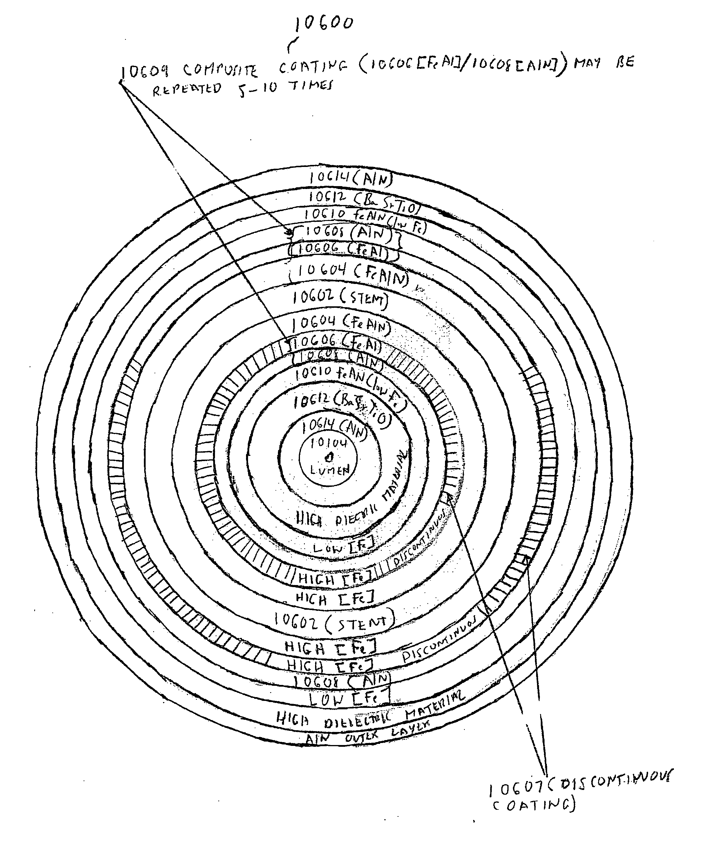
[0085] In the first part of this specification, certain assemblies that contain nanomagnetic material, and / or certain processes for making nanomagnetic material, will be briefly described. Thereafter, in the second part of this specification, an improved stent assembly whose lumen is readily imageable under magnetic resonance imaging conditions will be described.

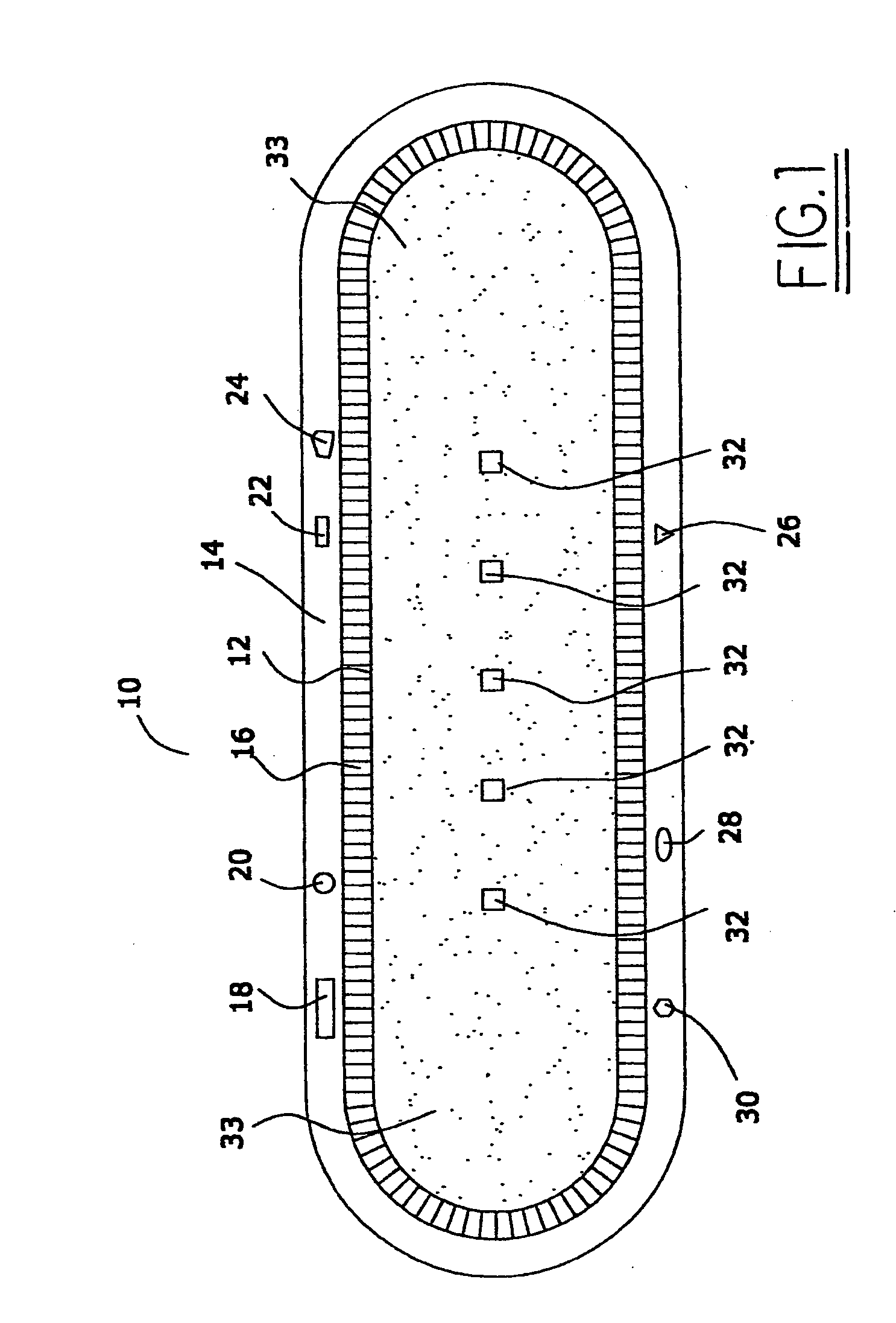
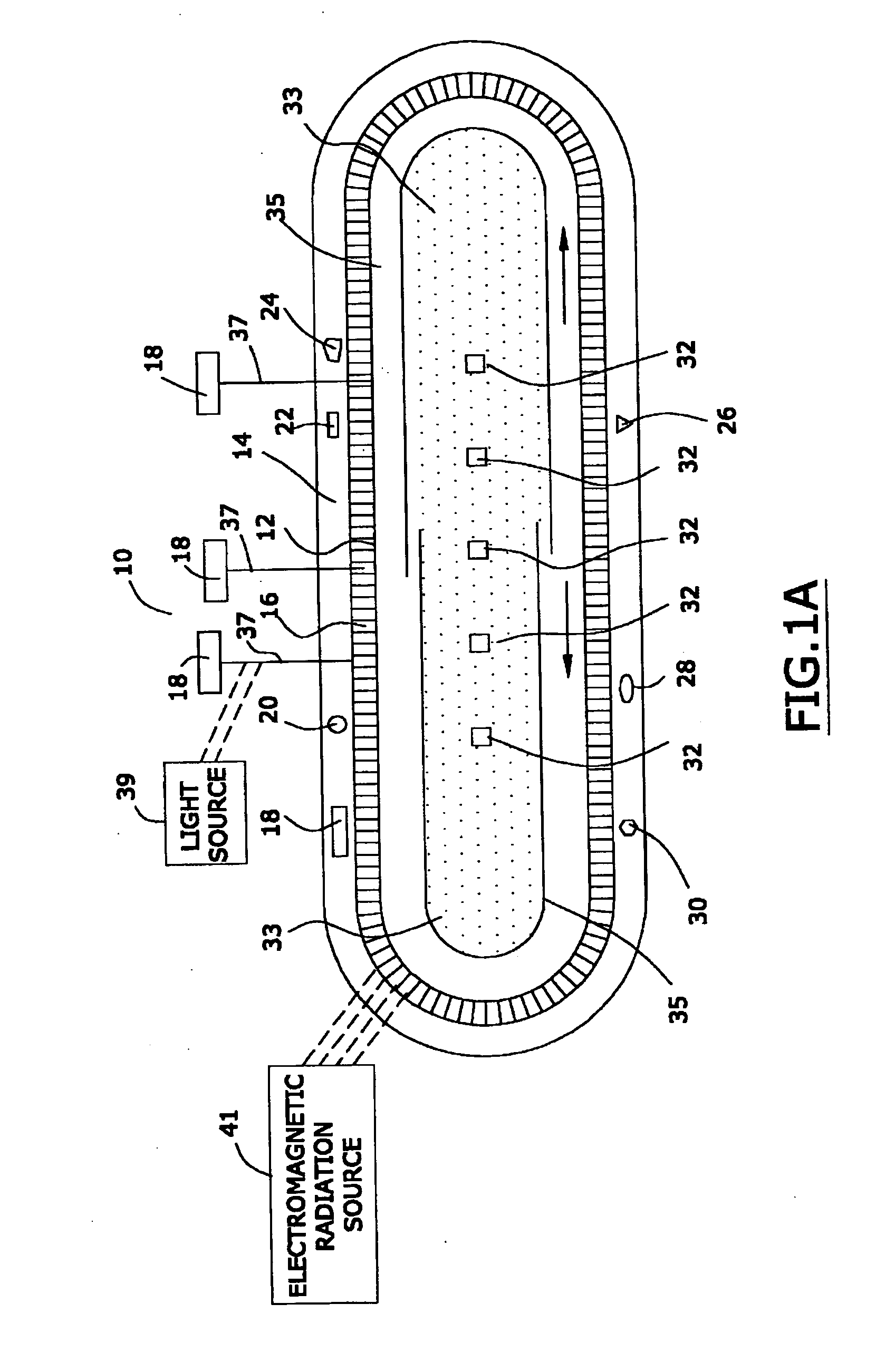
[0086]FIG. 1 is a schematic diagram of a preferred seed assembly 10 of this invention that may, in one preferred embodiment, contain nanomagnetic material. The FIGS. 1 and 1A of this specification are substantially identical to the FIGS. 1 and 1A of published United States patent application US 2005 / 0025797, published on Feb. 5, 2005, the entire disclosure of which is hereby incorporated by reference into this specification; in particular, and without limitation, the disclosure of pages 2 through 40 of such published patent application, are hereby incorporated by reference into this specification.

[0087] Referring again to ...


PUM

PropertyMeasurementUnit
frequencyaaaaaaaaaa
sizeaaaaaaaaaa
sizeaaaaaaaaaa

Abstract

A medical device comprised of a coating that inhibits distortion of medical resonance images taken of the device. When the device is exposed to radio frequency electromagnetic radiation with a frequency of from 10 megahertz to about 200 megahertz, at least 90 percent of such radio frequency electromagnetic radiation penetrates to the lumen of the device; and the concentration of the radio frequency electromagnetic radiation that penetrates to the lumen of the device is substantially identical at different points within such interior. The coating is comprised of magnetic material with an average particle size of less than about 40 nanometers.

Description

CROSS-REFERENCE TO RELATED PATENT APPLICATION [0001] This patent application is a continuation in part of each of applicants' copending patent application Ser. No. 10 / 887,521 (filed on Jul. 7, 2004), Ser. No. 10,867,517 (filed on Jun. 14, 2004), Ser. No. 10 / 810,916 (filed on Mar. 26, 2004), Ser. No. 10 / 808,618 (filed on Mar. 24, 2004), Ser. No. 10 / 786,198 (filed on Feb. 25, 2004), Ser. No. 10 / 780,045 (filed on Feb. 17, 2004), Ser. No. 10 / 747,472 (filed on Dec. 29, 2003), Ser. No. 10 / 744,543 (fled on Dec. 22, 2003), Ser. No. 10 / 442,420 (filed on May 21, 2003), and Ser. No. 10 / 409,505 (flied on Apr. 8, 2003). The entire disclosure of each of these patent applications is hereby incorporated by reference into this specification.FIELD OF THE INVENTION [0002] A medical device comprised of a coating that inhibits distortion of medical resonance images taken of the device. When the device is exposed to radio frequency electromagnetic radiation with a frequency of from 10 megahertz to about ...

Claims


Application Information

Patent Timeline
Patent Type & Authority Applications(United States)
IPC IPC(8): A61L31/08A61L31/18A61N1/16A61N2/00A61N2/06H02J7/00
CPCA61L31/082A61L31/18A61N2/06A61N2/002A61N1/16
Inventor WANG, XINGWUGREENWALD, HOWARD J.
Owner BIOPHAN TECH
Why Eureka
Try Eureka