
Plasma processing apparatus for powder and plasma processing method for powder

a technology of plasma processing apparatus and plasma, which is applied in the direction of plasma technique, transportation and packaging, material granulation, etc., can solve the problems of difficult application to industrial production, and achieve the effect of efficient processing and effective apparatus durability

Active Publication Date: 2005-08-25
HITACHI METALS LTD
View PDF4 Cites 22 Cited by
  • Summary
  • Abstract
  • Description
  • Claims
  • Application Information

AI Technical Summary

Benefits of technology

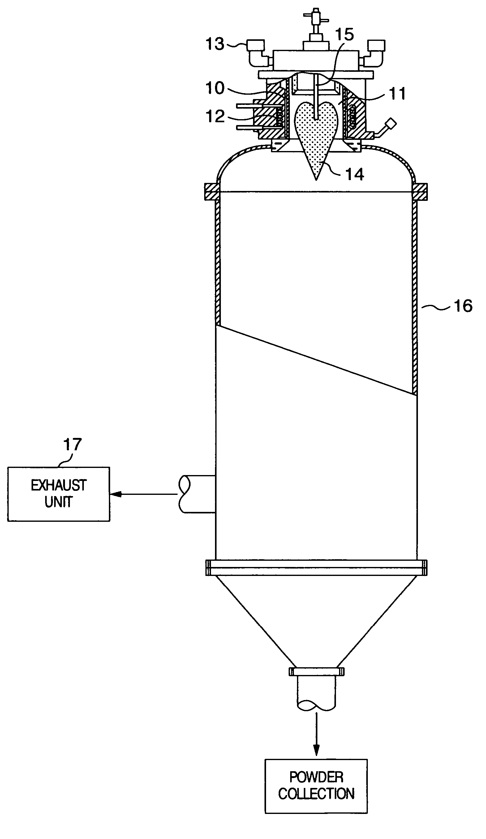
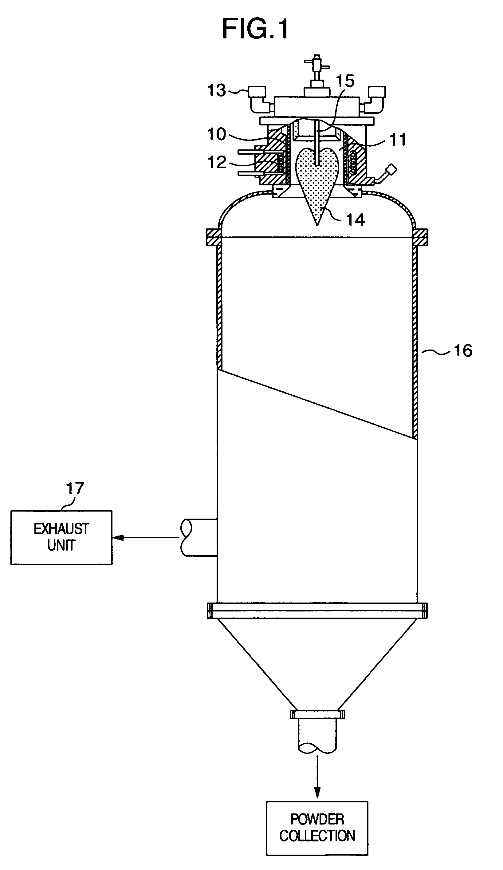
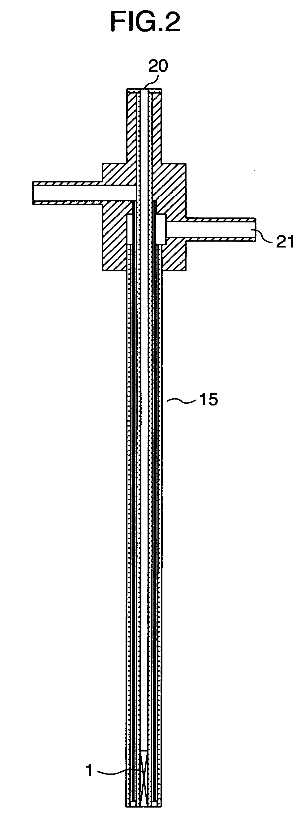
The present invention provides a plasma processing apparatus for powder and a plasma processing method for powder that can make effective use of plasma energy to increase processing efficiency. The apparatus includes a powder supply nozzle that is positioned radially centrally of a high-frequency coil. The nozzle has a revolving flow forming device that causes a carrier gas and powder material to form a revolving flow with an axis directed axially of the high-frequency coil. The apparatus can achieve a rapid increase in processing efficiency of powder and is effective in manufacturing a base powder for hot isostatic pressing. The invention is effective in industrial production and can be easily applied to plasma processing.

Problems solved by technology

However, the technique proposed in the above document by C. C. Berndt involves a problem of increased control factors because of the use of a third gas as a drive force for diffusion of powder, and a problem of the necessity of maintaining a mechanism, which serves to supply the third gas and is exposed to high temperature, in a controllable state, and the inventors of the present application have not been able to apply the technique to industrial production.
However, powder particles connect together due to an increased supply of the powder material and melt as they are, to show a tendency that powder containing coarse particles results, thus making application to industrial production difficult.

Method used


Image

  • Plasma processing apparatus for powder and plasma processing method for powder
  • Plasma processing apparatus for powder and plasma processing method for powder
  • Plasma processing apparatus for powder and plasma processing method for powder

Examples


example 1

[0046] Using a thermal plasma apparatus shown in FIG. 1, the spiral-shaped plate 1 shown in FIG. 4 was mounted and an outlet of the tip member 2 was modified in shape, influences of which on powder processing were examined.

[0047]FIGS. 5A to 5D show shapes of nozzle tip ends. First, FIG. 5A shows a normal straight nozzle having an inside diameter of 4.5 mm and provided with no revolving flow forming device.

[0048]FIG. 5B shows a nozzle provided at a tip end thereof with a spiral-shaped plate 1. As the spiral-shaped plate, one formed by twisting a flat sheet of JIS SUS304 having a thickness of 0.3 mm was used.

[0049]FIG. 5C shows a nozzle, in which a transition space 3 is defined 15 mm distant from a tip end thereof and a spiral-shaped plate 1 is mounted in a position distant from the tip end. FIG. 5D shows a nozzle, which is of the same construction as that of the nozzle shown in FIG. 3, and in which a transition space 3 is defined 15 mm distant from a tip end thereof, the tip end h...


PUM

PropertyMeasurementUnit
temperatureaaaaaaaaaa
diameteraaaaaaaaaa

Abstract

A plasma processing apparatus for powder, and a plasma processing method of powder, in which a powder supply nozzle is provided to supply a powder material into plasma flame generated inside a high-frequency coil, the powder supply nozzle arranged substantially radially centrally of the high-frequency coil comprises a revolving flow forming device, for example, a spiral-shaped plate, to cause a carrier gas and the powder material to form therein a revolving flow with an axis thereof directed axially of the high-frequency coil, and the revolving flow is discharged from an outlet at an end of the nozzle. More preferably, a transition space is provided between the outlet at the end of the nozzle and the revolving flow forming device, and the outlet at the end of the nozzle is made small in diameter.

Description

TECHNICAL FIELD [0001] The present invention relates to a plasma apparatus for powder to highly efficiently spheroidize powder at a high rate of spheroidization, and a plasma processing method for powder. BACKGROUND OF THE INVENTION [0002] Conventionally, there have been used in the field of powder metallurgy compression molding, in which powder is packed in a mold and compressed in order to mold a product with powder as a raw material, a method of placing a compressed green compact in a high-temperature furnace to sinter the same, and the like. In recent years, a demand for high purity and high density of products has become great, and so there has been used a hot isostatic pressing method of vacuum-sealing powder in a can made of thin steel sheet or glass, placing the can in a furnace, which is filled with gases such as Ar, N2, or the like, and applying high temperature and high pressure thereto to achieve compression sintering. [0003] In case of molding a product by the hot isost...

Claims


Application Information

Patent Timeline
Patent Type & Authority Applications(United States)
IPC IPC(8): B01J2/00H05H1/30B01J19/08B22F1/065B22F1/142B22F9/00B22F9/06B22F9/08C23C4/00H05H1/42
CPCB01J4/002B01J19/088B01J2219/0869B01J2219/0879B01J2219/0894B22F1/0048B22F1/0085H05H1/42B22F2999/00B22F1/0011B22F2202/13B22F1/065B22F1/142B22F1/05
Inventor UESAKA, SHUJIROHHAN, GANGHIRAKAWA, EIJI
Owner HITACHI METALS LTD
Learn More