Apparatus and method for controlling ink or paint temperature in a printing device

a printing device and ink temperature technology, applied in printing presses, printing presses, rotary intaglio printing presses, etc., can solve the problems of poor ink/print transfer, time-consuming process, and downtime of cleaning machines, so as to reduce the evaporation of solvents in the ink, and the ink temperature is low

Inactive Publication Date: 2005-08-25
TAYLOR MADE GOLF
View PDF8 Cites 21 Cited by
  • Summary
  • Abstract
  • Description
  • Claims
  • Application Information

AI Technical Summary

Benefits of technology

[0008] In accordance with the present invention, a pad printing machine is provided that comprises a pad transfer mechanism, an ink cup or reservoir, a cliche plate, a support plate, an excess ink removal device and an ink temperature control apparatus. The ink temperature control apparatus maintains the temperature of the ink at a predetermined level. The ink temperature control apparatus includes a temperature control element adapted to lower the temperature of the ink in the ink cup. A temperature sensor senses the temperature of either the ink in the ink cup or the ink cup surface. A signal is sent to the temperature control apparatus, which, based on the received signal, adjusts the temperature of the temperature control element to lower the temperature of the ink and maintaining the temperature of the ink at a level that reduces evaporation of solvents in the ink.

Problems solved by technology

As ink viscosity increases, when the doctor blade or other type of wiping or scraping device removes excess ink from the plate, the ink tends to smear on the plate resulting in poor ink / print transfer onto the ball.
This results in machine downtime for cleaning, etc. which can be a time consuming process.
In addition, evaporation of the solvents produces undesirable volatile vapor in the work environment.

Method used


Image

  • Apparatus and method for controlling ink or paint temperature in a printing device
  • Apparatus and method for controlling ink or paint temperature in a printing device
  • Apparatus and method for controlling ink or paint temperature in a printing device

Examples


Embodiment Construction

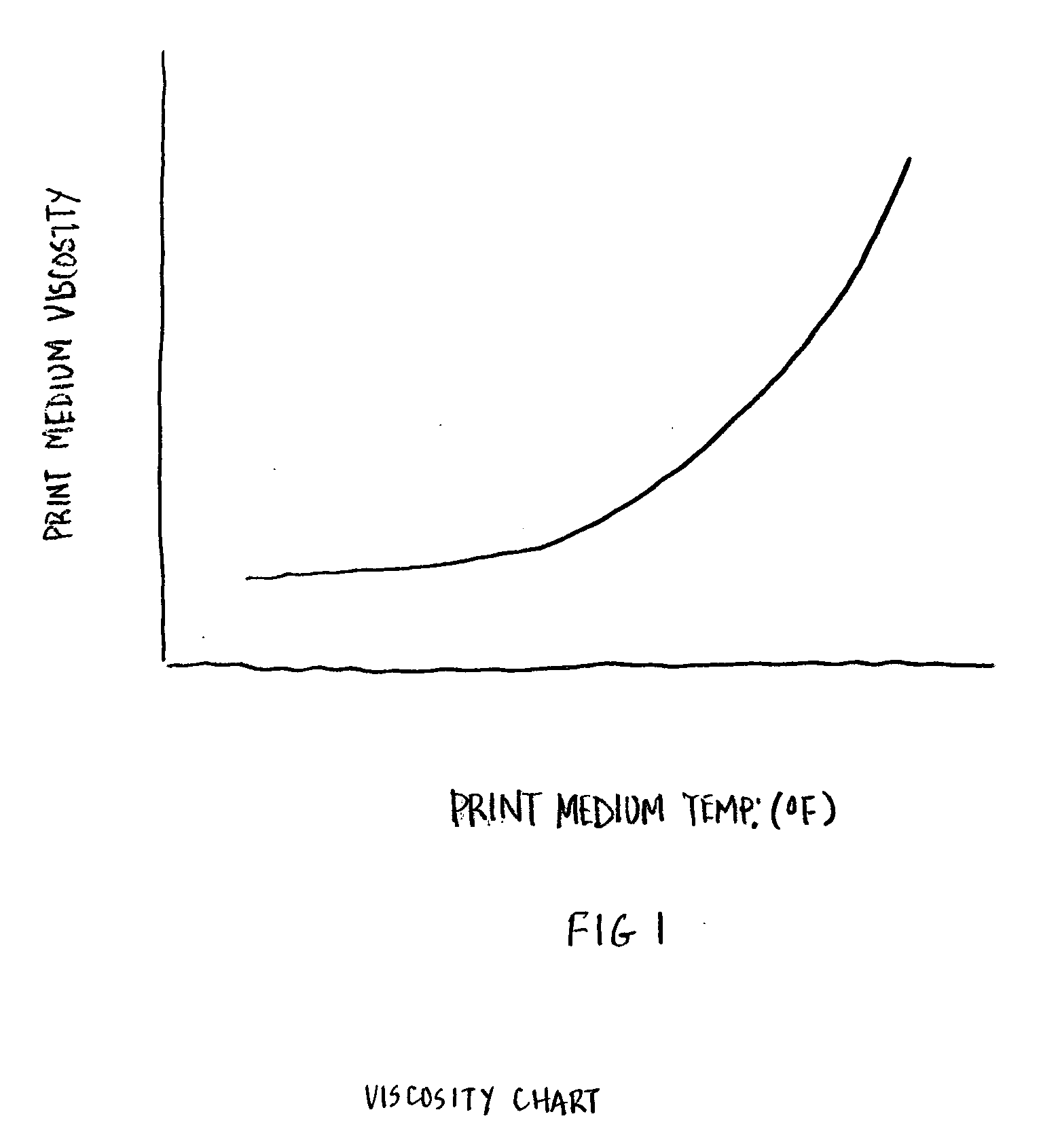
[0027] Referring to FIG. 1, the temperature of a solvent-based ink directly affects the viscosity of the ink. As the temperature of the ink increase, the solvents used in the ink to maintain a specific viscosity begin to evaporate out. As this evaporation takes place, the viscosity of the ink gradually increases, thereby increasing the likelihood of smearing, degrading the print transfer and making it more difficult to clean.

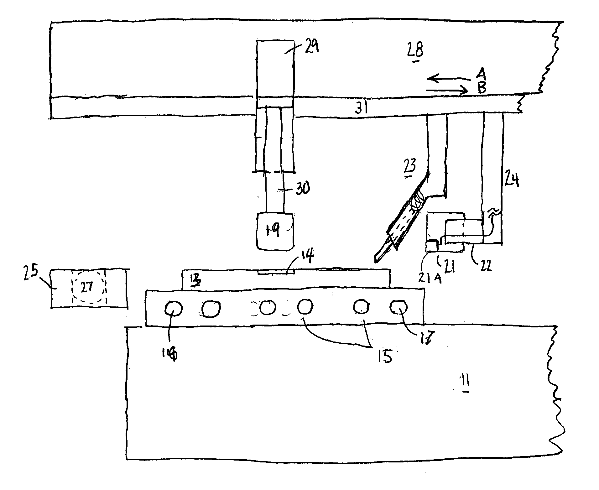
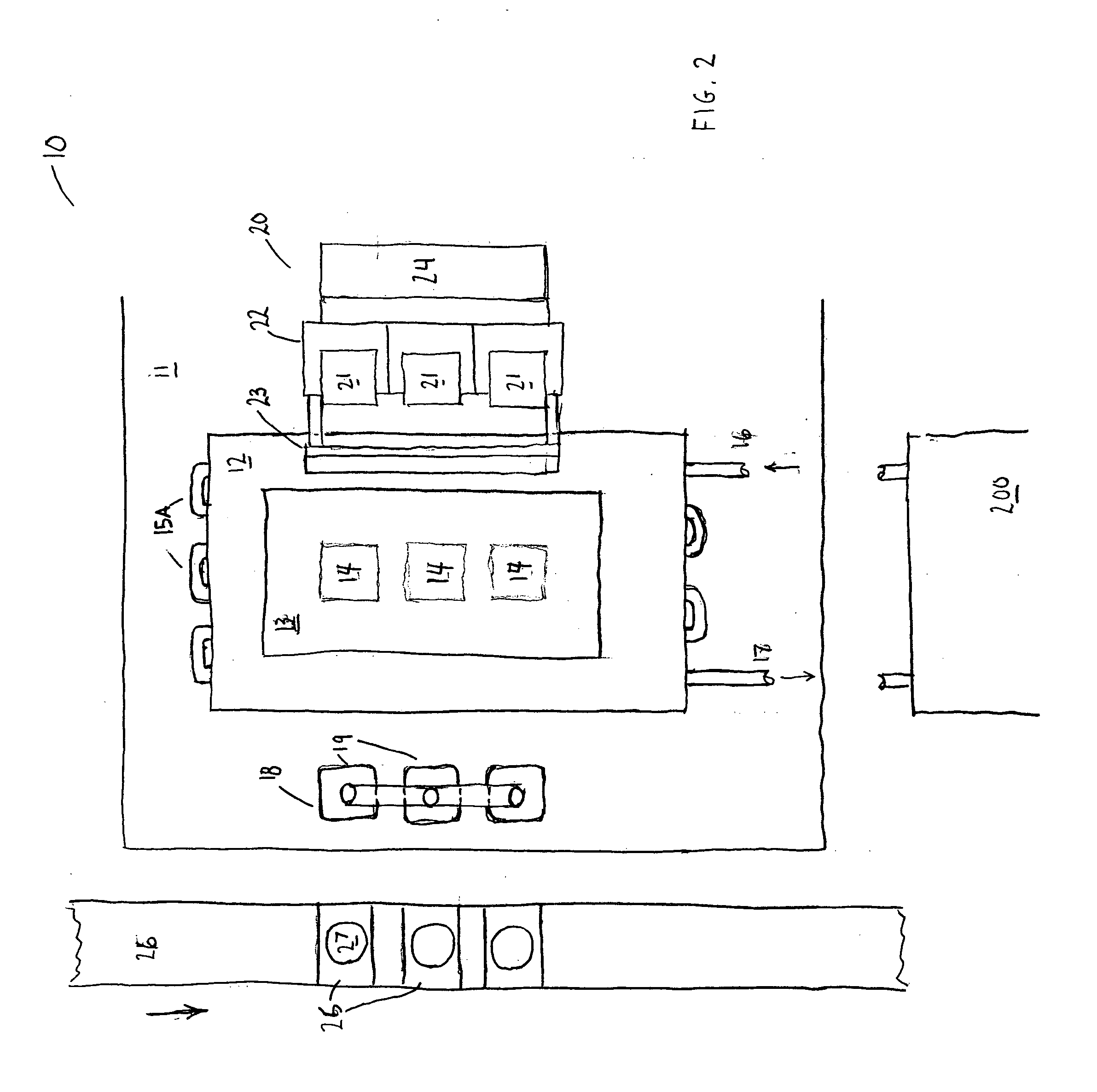
[0028]FIGS. 2-4 illustrate one aspect of the present invention. A pad printing machine 10 has a base 11. A support plate 12 is positioned on top of base plate 11. A cliché plate 13 is positioned on top of and is clamped to support plate 12. Cliché plate 13 carries one or more engraved areas 14 that represent the art work or other indicia that is to be printed on an object 27. As shown in FIG. 4, support plate 12 has a series of channels 15 formed therein, through which a unshaped piping assembly 15A is held. A temperature sensor 15B (FIG. 4) is mounted to suppo...


PUM


Abstract

Apparatus and methods of controlling the temperature of printing ink or paint in a pad printing apparatus are described. The apparatus comprise temperature control elements that are connected to a chiller unit. Temperature sensors on a support plate or ink cup, or both monitor the temperature of the ink cup and/or ink. As the temperature of the ink in an ink cup rises due to ambient air temperature in the working environment, a chill medium is applied to the support plate, ink cup, ink or any combination thereof to cool the temperature of the ink thereby reducing evaporation of solvents in the ink to maintain a relatively constant ink viscosity.

Description

CROSS-REFERENCE TO RELATED APPLICATIONS [0001] A claim of benefit is made to U.S. provisional application Ser. No. 60 / 492,503, filed Aug. 5, 2003, the contents of which are incorporated herein by reference.FIELD OF THE INVENTION [0002] The present invention relates generally to printing, and more particularly, to an improved control of ink or paint temperature in a pad transfer printing device. BACKGROUND OF THE INVENTION [0003] In the golf ball industry, the surface of a golf ball usually bears a mark, such as a number, a manufacturer name, and the like. Conventionally, the marked portion is formed on the golf ball surface primarily by a transfer printing method or a pad printing method. In the transfer printing method, a transfer foil which has been formed on transfer paper through printing is transferred onto a marking-portion forming surface of the golf ball through application of heat and pressure. Pad printing is used for printing images on curved or other non-flat surfaces su...

Claims


Application Information

Patent Timeline
Patent Type & Authority Applications(United States)
IPC IPC(8): B41F9/01B41F17/00B41F31/00
CPCB41F31/002B41F17/001
Inventor BRUNO, BRIANGIANFORCARO, GREGHEDRICK, JEREMY
Owner TAYLOR MADE GOLF
Why Eureka
Try Eureka