
Fluid actuating apparatus and method for manufacturing a fluid actuating apparatus, and electrostatically-actuated fluid discharge apparatus and process for producing an electrostatically-actuated fluid discharge apparatus

a technology of fluid actuating and fluid discharge, which is applied in the direction of chairs, applications, coatings, etc., can solve the problems of lack of repulsion force, and achieve the effects of suppressing power consumption, increasing thickness, and strengthening the support pos

Inactive Publication Date: 2005-08-25
SONY CORP
View PDF2 Cites 7 Cited by
  • Summary
  • Abstract
  • Description
  • Claims
  • Application Information

AI Technical Summary

Benefits of technology

[0024] In the fluid actuating apparatus according to an embodiment of the present invention, the diaphragm-side electrode is formed so that it passes through the support post and extends to and covers part of the bottom of the support post, or it extends from the support post to another, and therefore, as compared to the construction in which the diaphragm-side electrode is formed so that it covers the whole of the bottom of the support post, the amount of the charge, which does not contribute to deformation of the diaphragm and which is stored on the bottom of the support post, is small, thus suppressing a waste of the power consumption. In addition, in the construction in which the diaphragm-side electrode is formed so that it passes through the support post and extends to and covers part of the bottom of the support post, with respect to the strength of the diaphragm, there is an advantage in that the support post has a larger thickness by the thickness of the diaphragm-side electrode than that in the construction in which the diaphragm-side electrode is formed so that it does not extend to the support post, and thus the support post gets stronger.
[0025] The method for manufacturing a fluid actuating apparatus according to another embodiment of the present invention, includes the step for forming a diaphragm-side electrode through the second insulating film on the upper surface of the sacrifice layer pattern, the sidewall of the sacrifice layer pattern, and part of the bottom of the support post-forming region, and hence the diaphragm-side electrode is formed so that it passes through the support post and extends to and covers part of the bottom of the support post. Therefore, there can be produced a fluid actuating apparatus having a construction such that, as compared to the construction in which the diaphragm -side electrode is formed so that it covers the whole of the bottom of the support post, the amount of the charge, which does not contribute to deformation of the diaphragm and which is stored on the bottom of the support post, is small, thus suppressing a waste of the power consumption. In addition, with respect to the strength of the diaphragm, there is an advantage in that the fluid actuating apparatus can be produced so that the support post has a larger thickness by the thickness of the diaphragm-side electrode than that in the construction in which the diaphragm-side electrode is formed so that it does not extend to the support post, and thus the support post is stronger.
[0026] The method for manufacturing a fluid actuating apparatus according to an embodiment of the present invention includes the steps of forming a diaphragm-side electrode through the second insulating film on the sacrifice layer pattern including a portion between the support post-forming regions. Therefore, there can be produced a fluid actuating apparatus having a construction such that, as compared to the construction in which the diaphragm-side electrode is formed so that it covers the whole of the bottom of the support post, the amount of the charge, which does not contribute to deformation of the diaphragm and which is stored on the bottom of the support post, is small, thus suppressing a waste of the power consumption.
[0027] The electrostatically-actuated fluid discharge apparatus according to an embodiment of the present invention includes the fluid actuating apparatus according to an embodiment of the present invention, and therefore has not only the above-mentioned advantages obtained by the fluid actuating apparatus according to an embodiment of the present invention, but also an advantage in that there can be provided the electrostatically-actuated fluid discharge apparatus having high fluid actuating force and having an increased density of fluid discharge sections, e.g., nozzles for liquid, or discharge outlets for gas.
[0028] The method for manufacturing an electrostatically-actuated fluid discharge apparatus according to an embodiment of the present invention includes the method for manufacturing a fluid actuating apparatus according to an embodiment of the present invention, and therefore has not only the above-mentioned advantages obtained by the method for manufacturing a fluid actuating apparatus according to an embodiment of the present invention, but also an advantage in that the electrostatically-actuated fluid discharge apparatus can be produced easily with high precision. Further, there is an advantage in that the electrostatically-actuated fluid discharge apparatus, for example, an ink-jet printer head having a diaphragm, a pressure chamber, a discharge section (nozzle or discharge outlet), and the like can be produced by, e.g., surface micromachining without using lamination.
[0029] A task of reducing a waste of the power consumption to suppress the power consumption while achieving a diaphragm having satisfactory repulsion force for actuation of a fluid, and preventing the stress concentration on the diaphragm-side electrode and the support post is achieved by employing a structure in which the diaphragm-side electrode is formed so that it extends to and passes through the support post or a structure in which the diaphragm-side electrode is formed so that it extends from the support post to another without complicating the process for production.

Problems solved by technology

In this fluid actuating apparatus having a construction in which the diaphragm-side electrode separately formed has a rectangular form having such a size that the diaphragm-side electrode does not extend to the support post, when a voltage is applied, a stress due to deformation of the diaphragm concentrates on a portion between the electrode and the support post to weaken the diaphragm, leading to a problem in that there is a lack of the repulsion force.

Method used


Image

  • Fluid actuating apparatus and method for manufacturing a fluid actuating apparatus, and electrostatically-actuated fluid discharge apparatus and process for producing an electrostatically-actuated fluid discharge apparatus
  • Fluid actuating apparatus and method for manufacturing a fluid actuating apparatus, and electrostatically-actuated fluid discharge apparatus and process for producing an electrostatically-actuated fluid discharge apparatus
  • Fluid actuating apparatus and method for manufacturing a fluid actuating apparatus, and electrostatically-actuated fluid discharge apparatus and process for producing an electrostatically-actuated fluid discharge apparatus

Examples


example 1

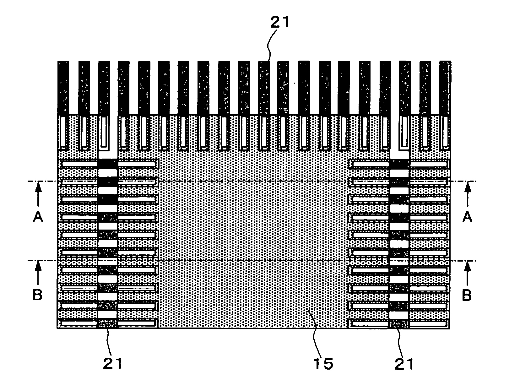
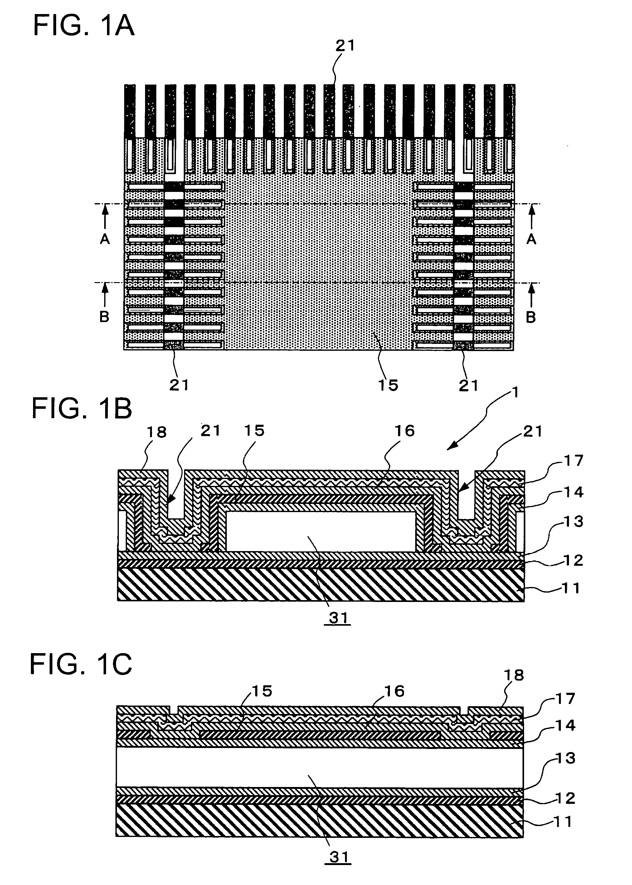
[0067] The fluid actuating apparatus according to the first embodiment of the present invention will be described with reference to FIGS. 1A-1C. FIG. 1A shows part of a plan view of the layout, FIG. 1B shows a diagrammatic cross-sectional structure taken along the line A-A of FIG. 1A, and FIG. 1C shows a diagrammatic cross-sectional structure taken along the line B-B of FIG. 1A. The scale of FIG. 1A and that of FIG. 1B, FIG. 1C are not the same. Fluid actuating apparatuses are actually arranged in a line, but the figures show a single fluid actuating apparatus, which is described below.

[0068] As shown in FIGS. 1A-1C, a substrate-side electrode 12, which includes a conductor thin film and which is common to another fluid actuating apparatus (not shown), is formed on a substrate 11 having at least a surface formed from an insulating layer. A first insulating film 13 is formed on the substrate-side electrode 12. A second insulating film 14 is formed on the first insulating film 13 so ...

example 2

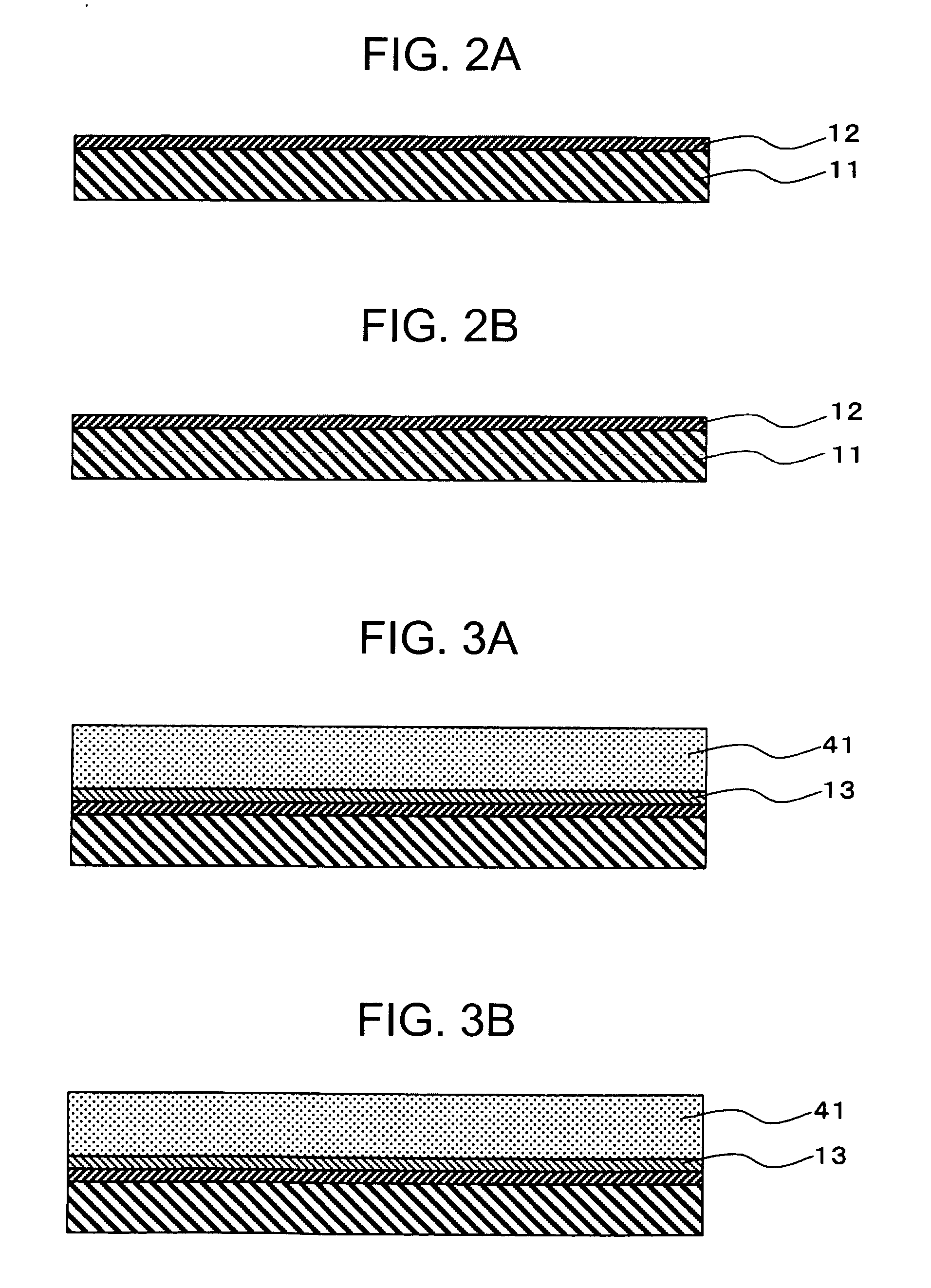
[0079] The method for producing a fluid actuating apparatus according to the first embodiment of the present invention will be described with reference to the views of FIGS. 2A to 12B showing the steps in the production process. The views of FIGS. 2A to 12B showing the steps in the production process mainly show cross-sectional structures at positions similar to the positions of the cross-section taken along the line A-A and the cross-section taken along the line B-B shown in the plan view of the layout of FIG. 1A. In FIGS. 4A-4C, a plan view of the layout of the sacrifice layer pattern is also shown.

[0080] As shown in FIGS. 2A-2B, a substrate 11 having at least an insulating surface is prepared. As the substrate 11, for example, in the present Example, a substrate comprising an insulating film, e.g., a silicon oxide film formed on a silicon substrate is used. A common substrate-side electrode 12 is formed on the substrate 11. In the present Example, the substrate-side electrode 12...

example 3

[0096] Next, the electrostatically-actuated fluid discharge apparatus according to the first embodiment of the present invention will be described with reference to the diagrammatic perspective view of FIG. 13 and the diagrammatic cross-sectional views of FIGS. 14A-14B. In this Example, an electrostatic head is described as an example of the electrostatically-actuated fluid discharge apparatus using the fluid actuating apparatus of the present invention.

[0097] First, as shown in FIG. 13, an electrostatically-actuated fluid discharge apparatus (electrostatic head) 1 according to the present embodiment comprises a fluid actuating apparatus 2 comprising a plurality of diaphragms 17 actuated (vibrated) by electrostatic force, which diaphragms are arranged in a line with high density, and a so-called fluid feed zone 55 comprising a partition structure 54 which is disposed above the diaphragms 17 at the corresponding position, and which has formed therein a pressure chamber (so-called ca...


PUM

PropertyMeasurementUnit
thicknessaaaaaaaaaa
temperatureaaaaaaaaaa
pressure changeaaaaaaaaaa

Abstract

A fluid actuating apparatus is proposed, which includes: a diaphragm for providing a pressure change in fluid; a diaphragm-side electrode, formed for the diaphragm, for actuating the diaphragm; a substrate-side electrode formed so that it faces the diaphragm-side electrode; a space formed between the diaphragm-side electrode and the substrate-side electrode; and a support post, formed on the substrate-side electrode, for supporting the diaphragm-side electrode through the space. where the diaphragm-side electrode is formed so that it passes through the support post and extends to and covers part of the bottom of the support post.

Description

CROSS REFERENCE TO RELATED APPLICATION [0001] The present invention contains subject mater related to Japanese Patent Application JP2004-049131 filed in the Japanese Patent Office on Feb. 25, 2004, the entire contents of which being incorporated herein by reference. BACKGROUND OF THE INVENTION [0002] 1. Field of the Invention [0003] The present invention relates to a fluid actuating apparatus, which can prevent a stress from concentrating on a portion between an electrode and a support post wherein the stress is caused due to deformation of a diaphragm when a voltage is applied to the electrode for vibrating the diaphragm, while securing repulsion force of the diaphragm, and a method for manufacturing the fluid actuating apparatus, and an electrostatically-actuated fluid discharge apparatus using the fluid actuating apparatus and a method for manufacturing the electrostatically-actuated fluid discharge apparatus. [0004] 2. Description of Related Art [0005] In a printer which meets t...

Claims


Application Information

Patent Timeline
Patent Type & Authority Applications(United States)
IPC IPC(8): B41J2/045B41J2/16B41J2/055B41J2/14B81B3/00B81C1/00
CPCB41J2/14314A47C1/0342A47C7/506A47C1/025
Inventor YAMAGUCHI, MASANARI
Owner SONY CORP
Learn More