
System for separating and linking composite fibers

a technology of composite fibers and bundles, applied in the direction of document inserters, printing, transportation and packaging, etc., can solve the problems of premature hardening of resin, large expenditure of mechanical equipment, and inability to fully automate the production use of cutting and binding techniques, so as to prevent the wound package from slipping o

Active Publication Date: 2005-08-25
EHA SPEZIALMASCHENBAU
View PDF4 Cites 12 Cited by
  • Summary
  • Abstract
  • Description
  • Claims
  • Application Information

AI Technical Summary

Benefits of technology

[0014] In a process for separating and linking composite fibers using the filament winding technique, at least one fiber strand which is preferably impregnated with a matrix material is wound on a rotationally symmetrical base element driven in rotation and is then cut by means of a separating device. Subsequently, the cut fibers of the completed wound package are fixed on the latter, and the remaining fiber strand is passed to an adjacent new base element to which its free end is linked. It is a substantial advantage of the present invention that no auxiliary means such as a tube is required, as was the case with conventional systems. The rovings and / or tapes are directly fixed and cut on the product. After changing the support (mandrel or liner), the filament is automatically positioned on the next product and is wound. The winding operation continues until the previously programmed coverage of the base element by the resin-impregnated fibers is reached. Therefore, the installation can be operated in a very efficient way, particularly as the downtime is reduced to a minimum period required for maintenance purposes. That aspect in turn is important because of the quick hardening of the resin. Longer downtimes would disrupt the whole production.

Problems solved by technology

However, there is the disadvantage that the usual cutting and binding technique does not allow for a fully automated production using the filament winding process.
The result is an accumulation of wound roving ends in the respective parking position—which requires manual interventions to avoid long stops—and consequently the premature hardening of the resin, with the manual interventions impeding in turn a continuous operation.
The expenditures for mechanical equipment are considerable because all components except the main drive and the common drive for the traversing arms are required in duplicates.

Method used


Image

  • System for separating and linking composite fibers
  • System for separating and linking composite fibers
  • System for separating and linking composite fibers

Examples


Embodiment Construction

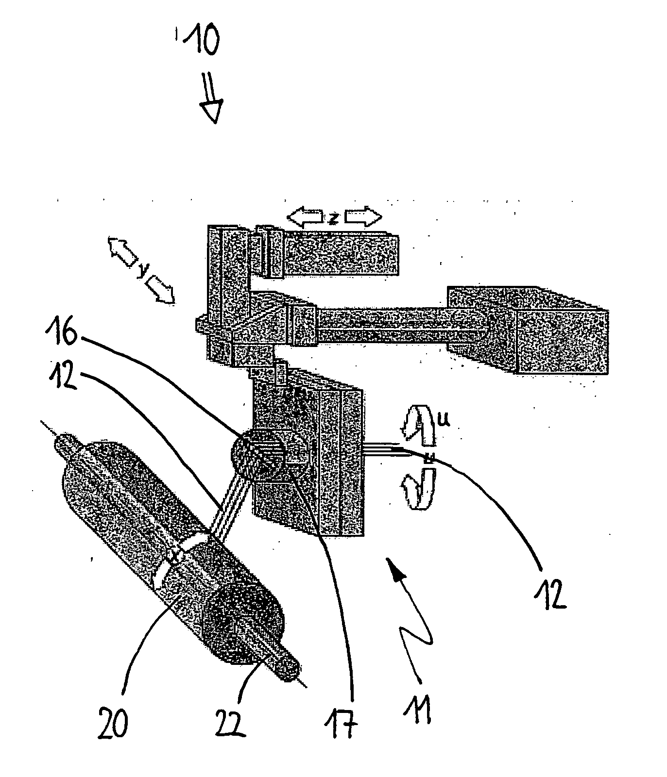
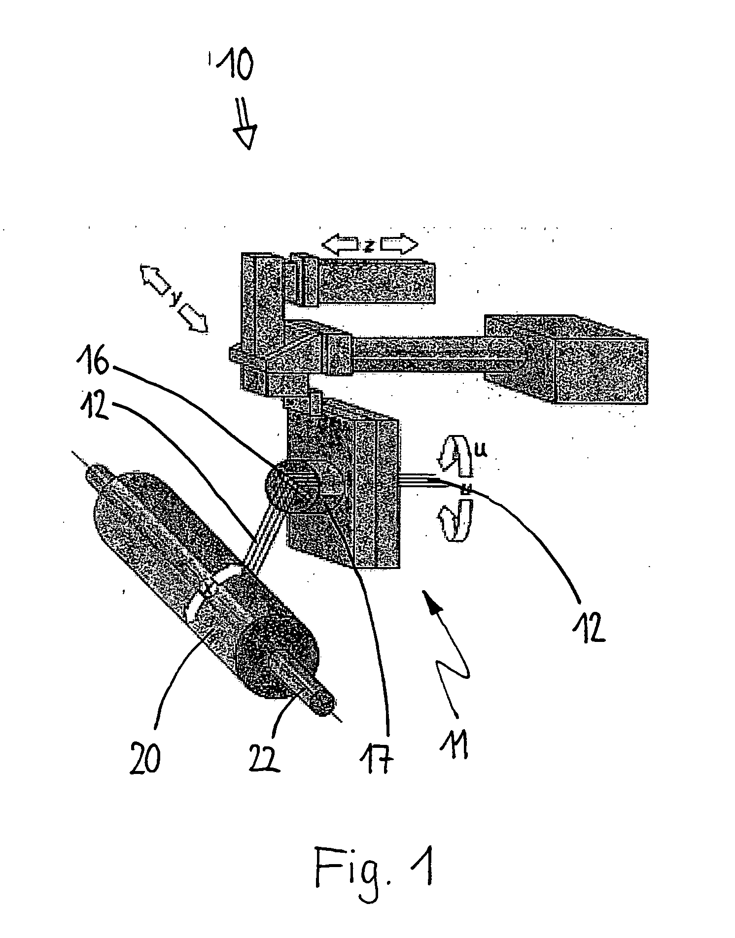
[0033] The system according to the invention is used in a filament winding installation 10 as schematically represented in FIG. 1 which may comprise a CNC-controlled single-spindle or multi-spindle lathe realized as a portal machine or a vertical machine and which may have drives to activate base elements 20 to be wound and a feeding device 11 for a fiber strand 12. The moving directions of the units and the components are illustrated by arrows. The axes of motion are referred to as x, y, z and u.

[0034] In the example described here, the base element 20 is a blow-moulded plastic cylinder 22 having curved ends and / or polar caps 24, one of them being provided with an intake or filler neck.

[0035] The fiber strand 12 may be a glass fiber tape consisting of 8 rovings with 1,200 tex each, for example. It is fed through an impregnation bath (not shown) where it is impregnated with resin, e.g. in a dipping infiltration process, and it finally reaches the base element 20 via a spool creel ...


PUM

PropertyMeasurementUnit
angleaaaaaaaaaa
widthaaaaaaaaaa
heightaaaaaaaaaa

Abstract

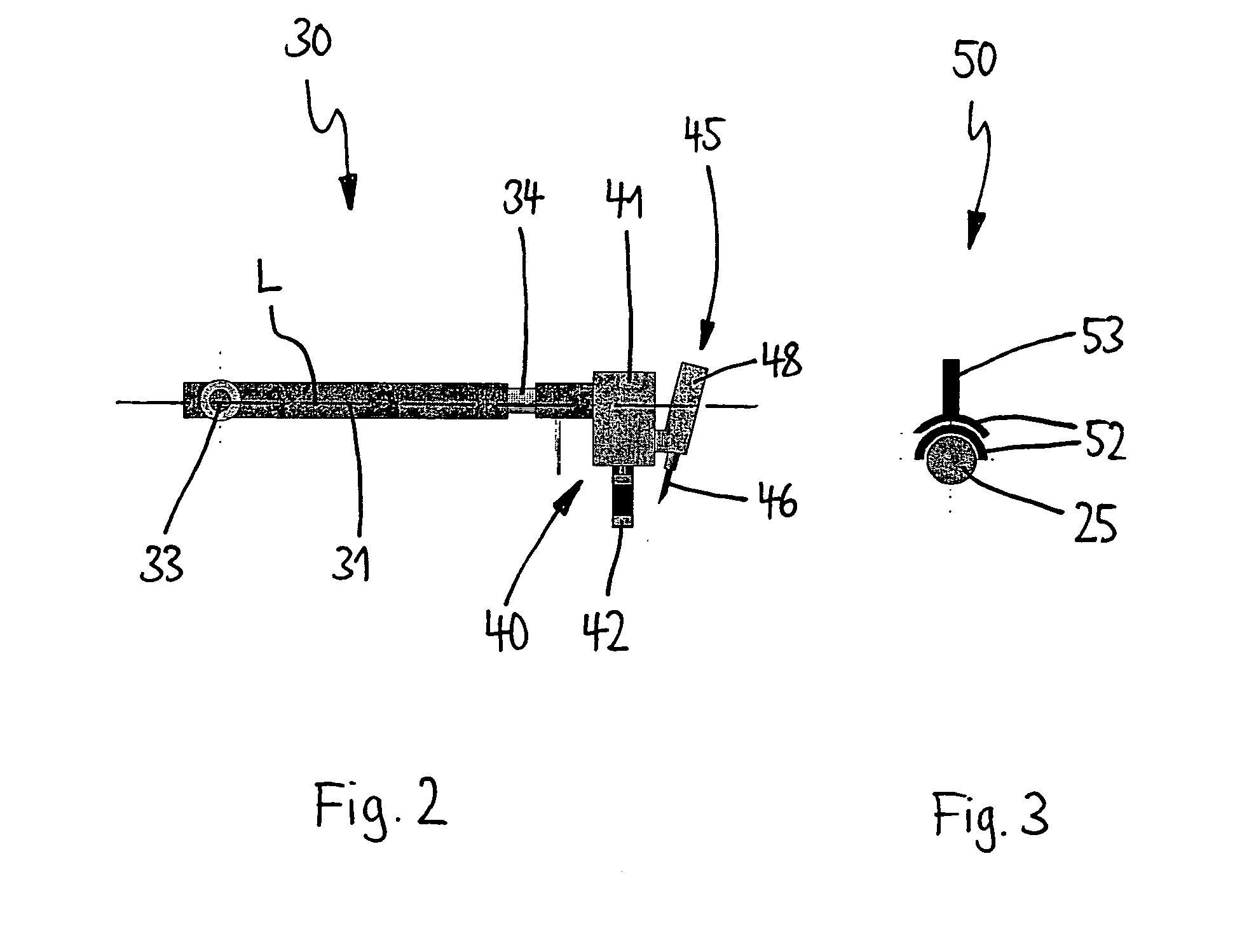
A system and process for separating and linking composite fibers, fiber bundles and the like in a filament winding installation (10) for the manufacture of rotationally symmetric wound packages (70) has a feeding device (11) for a fiber strand (12) impregnated with a matrix material which is wound on a rotatably driven base element (20). The system has at least one separating device (30) for cutting the fiber strand (12) and contacting the package-sided end (13) of the fiber strand (12) on the completed wound package (70). Also provided is at least one binding device (50) for linking the free end (14) of the fiber strand (12) with an adjacent new non-wound base element (20).

Description

CROSS-REFERENCE TO RELATED APPLICATIONS [0001] This application is a continuation of PCT / EP2002 / 011588 filed Oct. 17, 2002. This PCT application was not in English as published under PCT Article 21(2).FIELD OF INVENTION [0002] The present invention concerns a system for separating and linking composite fibers, fiber bundles and the like in a filament winding installation for the manufacture of rotationally symmetric wound packages. BACKGROUND OF THE INVENTION [0003] In a filament winding process, fiber strands are impregnated with resin and subsequently wound on a shaped support which may be a mandrel or a base element (liner), e. g. a plastic vessel. Once the winding operation is completed and the resin is cured, the shaped support is either removed from the wound package or it remains in place and becomes part of the wound package. Normally, winding is realized according to a predetermined pattern which is executed by means of a CNC control unit. The fiber strands generally consis...

Claims


Application Information

Patent Timeline
Patent Type & Authority Applications(United States)
IPC IPC(8): B29C53/80B65H81/00
CPCB29C53/8091
Inventor WEG, JOHANNES
Owner EHA SPEZIALMASCHENBAU
Learn More