
MEMS scanning mirror with trenched surface and tapered comb teeth for reducing inertia and deformation

Active Publication Date: 2005-08-25
ADVANCED NUMICRO SYST
View PDF10 Cites 39 Cited by
  • Summary
  • Abstract
  • Description
  • Claims
  • Application Information

AI Technical Summary

Benefits of technology

[0004] In one embodiment of the invention, a MEMS device includes a mirror having a top surface with trenches, a beam connected to the mirror, rotational comb teeth connected to the beam, and one or more springs connecting the beam to a bonding pad. Stationary comb tee

Problems solved by technology

It is known that when the mirror size and scanning speed increase, the mirror dynamic flatness deteriorates.
Without a flat mirror surface, the scanning mirror is of little use to many applications.
The undesired structural vibrations will increase the mirror dynamic deformation and result in degraded optical resolution.
Furthermore, some of the structural vibration modes may cause the rotationally movable and stationary comb teeth to come into contact and break the actuator all together.
Two or more structural vibration modes with close resonant frequencies may be coupled to produce high vibration amplitude that leads to hinge failure.

Method used


Image

  • MEMS scanning mirror with trenched surface and tapered comb teeth for reducing inertia and deformation
  • MEMS scanning mirror with trenched surface and tapered comb teeth for reducing inertia and deformation
  • MEMS scanning mirror with trenched surface and tapered comb teeth for reducing inertia and deformation

Examples


Embodiment Construction

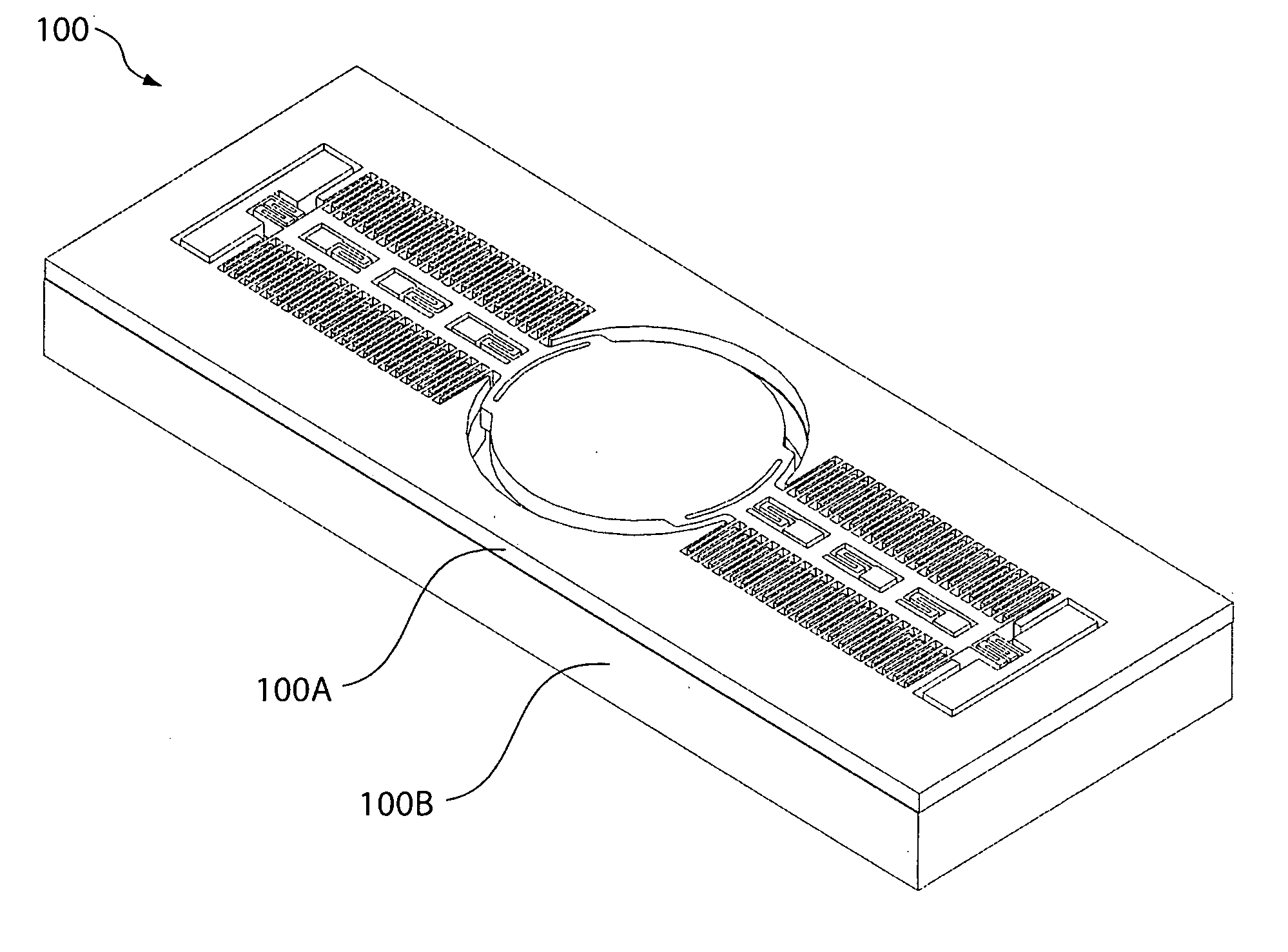
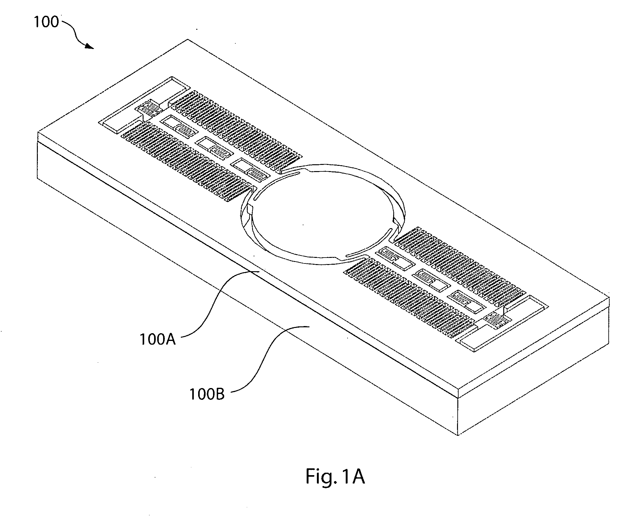
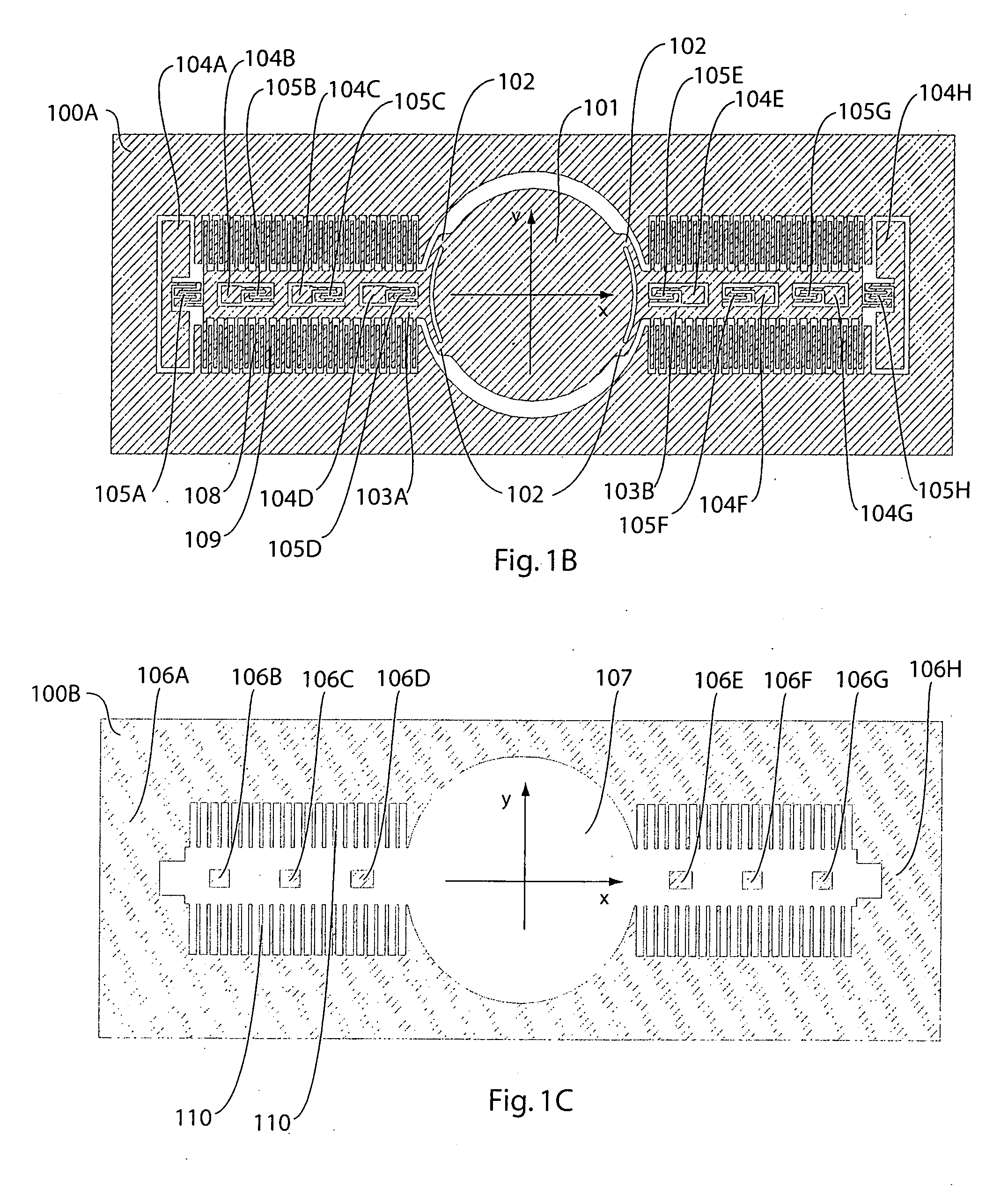
[0015]FIG. 1A illustrates a MEMS scanning mirror device 100 in one embodiment of the invention. Device 100 includes a top layer 100A (FIG. 1B) and a bottom layer 100B (FIG. 1C).

[0016] Referring to FIG. 1B, top layer 100A includes rotational comb teeth 108 that are connected on opposing sides of beam-like structures 103A and 103B. Proximate ends of beams 103A and 103B are connected by multiple support attachments 102 to opposing sides of a scanning mirror 101. In other words, each beam is connected at multiple locations to scanning mirror 101. The positions and the number of support attachments 102 can be refined through finite element analysis to improve the vibration stability and to minimize dynamic deformation of scanning mirror 101. By improving the vibration stability and reducing dynamic deformation of scanning mirror 101 with support attachments 102, the optical resolution of device 100 is improved.

[0017] Beams 103A and 103B are attached by eight serpentine springs / hinges 1...


PUM


Abstract

A micro-electro-mechanical system (MEMS) device includes a mirror having a top surface with trenches, a beam connected to the mirror, rotational comb teeth connected to the beam, and one or more springs connecting the beam to a bonding pad. The mirror can have a bottom surface for reflecting light. Stationary comb teeth can be interdigitated with the rotational comb teeth either in-plane or out-of-plane. Steady or oscillating voltage difference between the rotational and the stationary comb teeth can be used to oscillate or tune the mirror. The comb teeth can have a tapered shape.

Description

FIELD OF INVENTION [0001] This invention relates to micro-electro-mechanical system (MEMS) devices, and more particularly to MEMS scanning mirrors. DESCRIPTION OF RELATED ART [0002] Various electrostatic comb actuator designs for MEMS scanning mirrors have been proposed. The extensive applications of these devices include barcode readers, laser printers, confocal microscopes, projection displays, rear projection TVs, and wearable displays. Typically a MEMS scanning mirror is driven at its main resonance to achieve a large scan angle. To ensure a stable operation, it is crucial to ensure the mirror and its associated movable structure will vibrate in the desired mode shape at the lowest and main resonant frequency. In many applications, the mirror size has to be large and the mirror surface has to be flat to ensure high optical resolution. The mirror vibration / scanning speed also has to be fast for many applications. It is known that when the mirror size and scanning speed increase, ...

Claims


Application Information

Patent Timeline
IPC IPC(8): G02B26/08G02B26/10
CPCG02B26/0841
Inventor FU, YEE-CHUNG
Owner ADVANCED NUMICRO SYST
Learn More