Ultra wideband bow-tie slot antenna

a wideband, slot antenna technology, applied in the direction of slot antennas, antenna feed intermediates, antennas, etc., can solve the problems of inability to efficiently deliver or transmit power, difficult to realize and difficult to achieve high antenna efficiency in a wide frequency range. , the effect of small profile and light weigh

Inactive Publication Date: 2005-08-25
NAT INST OF INFORMATION & COMM TECH
View PDF8 Cites 13 Cited by
  • Summary
  • Abstract
  • Description
  • Claims
  • Application Information

AI Technical Summary

Benefits of technology

[0018] One object of the present invention is to provide a slot antenna which is small in profile, light weight

Problems solved by technology

However, when the receiving or transmitting frequency is different from the resonant frequency, the received or transmitted power cannot be delivered or radiated efficiently.
On the other hand, the non-resonant antenna can cover a wide frequency range, but realizing high antenna efficiency in a wide frequency range is very difficult.
Additionally, antennas having good frequency characteristics in a

Method used


Image

  • Ultra wideband bow-tie slot antenna
  • Ultra wideband bow-tie slot antenna
  • Ultra wideband bow-tie slot antenna

Examples


Embodiment Construction

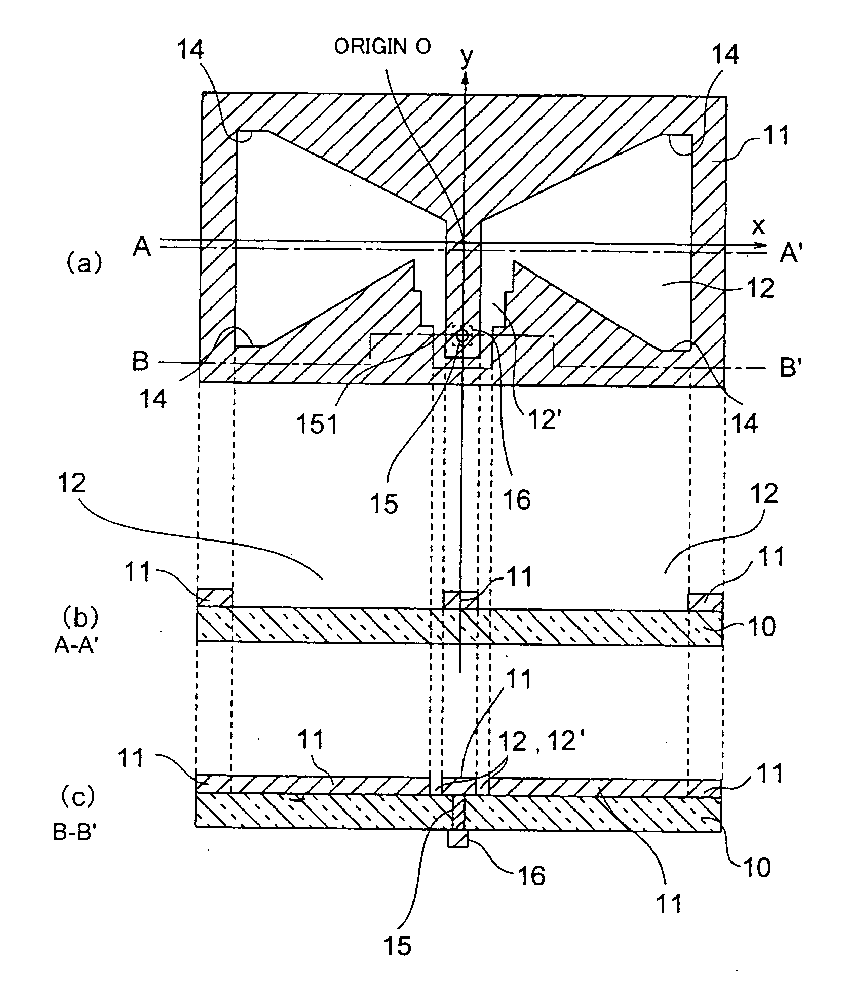
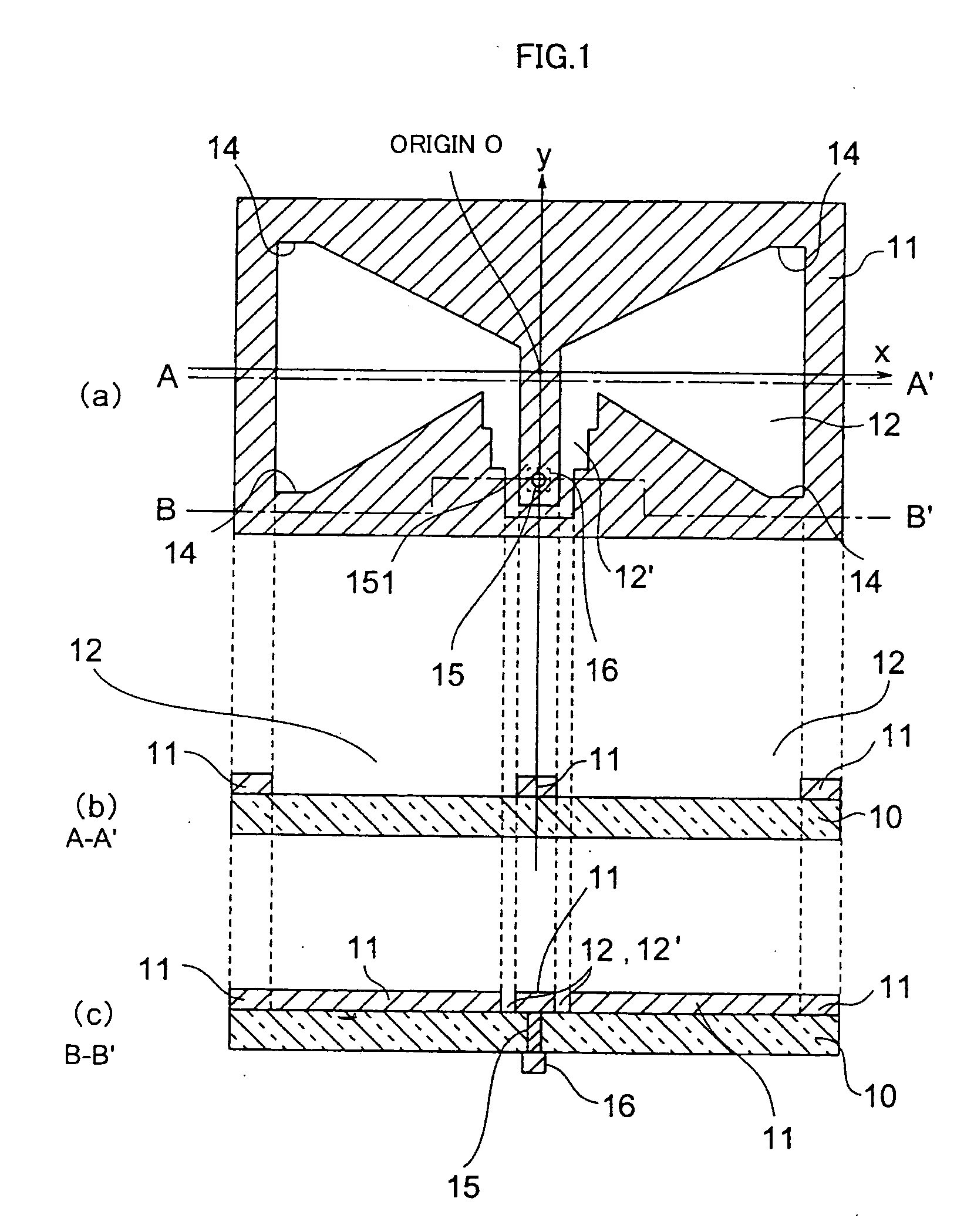
[0040]FIG. 1 is an embodiment of the slot antenna according to the present invention. FIG. 1(a) is a plane view of the slot antenna. FIG. 1(b) is a cross sectional view cut at A-A′ of the slot antenna. FIG. 1(c) is a cross sectional view cut at B-B′ of the slot antenna.

[0041] A metal layer 11 in FIG. 1 is layered on an insulation substrate 10. The substrate 10 is composed of, for example, Teflon or FR-4. The metal layer 11 is comprised of one of Cu, Al, Au, or Pt for example. A slot is formed in the metal layer 11. The figure of the slot 12 is like a bow-tie shape as shown in FIG. 1(a), and made inside the slot is an extension part 151 extending from a side of the slot antenna. As shown in FIG. 1, slot 12′ is narrowed step by step along the extension part 151. Narrowing it by three steps is an example. More steps or fewer steps are possible to narrow the slot, or the narrowing is possible. Four cut portions 14 are formed at each pointed edge of the slot 12. The cut portions 14 impr...


PUM


Abstract

A slot antenna includes an insulation substrate, a metal layer provided on the insulation substrate, a slot formed in the metal layer, and a feeding part connected to the metal layer. The slot is symmetric with respect to a centerline. When an x-y coordinate system is defined on the metal layer so that the y-axis is the symmetric line, the origin is the center of the slot antenna, and the x-axis through the origin is perpendicular to the y-axis, the width of the slot in the direction of the y-axis increasing in proportion to the absolute value of the x-axis.

Description

CROSS-REFERENCE TO RELATED APPLICATIONS [0001] This application is based upon and claims priority to Japanese Patent Application No. 2004-043395 filed Feb. 19, 2004, the contents of which are incorporated herein by reference. BACKGROUND OF THE INVENTION [0002] 1. Field of the Invention [0003] Antenna performance and size cause a large impact on the development of wireless devices. Moreover, development of wireless devices greatly depends on improvement of antenna characteristics and size. Designing a traditional antenna that provides fine typical parameters like bandwidth, efficiency and gain within a limited antenna volume is extremely hard. Antenna design is even more critical in devices using the ultra wideband frequency range (“UWB”) because communication in UWB systems uses very high data rates and low power densities. [0004] 2. Description of the Related Art [0005] Printed antennas are extensively used in various fields due to their many advantages such as their low profile, l...

Claims


Application Information

Patent Timeline
IPC IPC(8): H01Q5/00H01Q9/28H01Q13/00H01Q13/10
CPCH01Q9/285H01Q5/25H01Q13/10
Inventor YEKEH YAZDANDOOST, KAMYAKOHNO, RYUJI
Owner NAT INST OF INFORMATION & COMM TECH
Why Eureka
Try Eureka