

Magnetic sensing device, method of forming the same, magnetic sensor, and ammeter
- Summary
- Abstract
- Description
- Claims
- Application Information
AI Technical Summary
Benefits of technology
Problems solved by technology
Method used
Image

Examples
first embodiment
[0062] First, the configuration of a magnetic sensing device as a first embodiment of the invention will be described with reference to FIGS. 1A to 1C to FIG. 5.
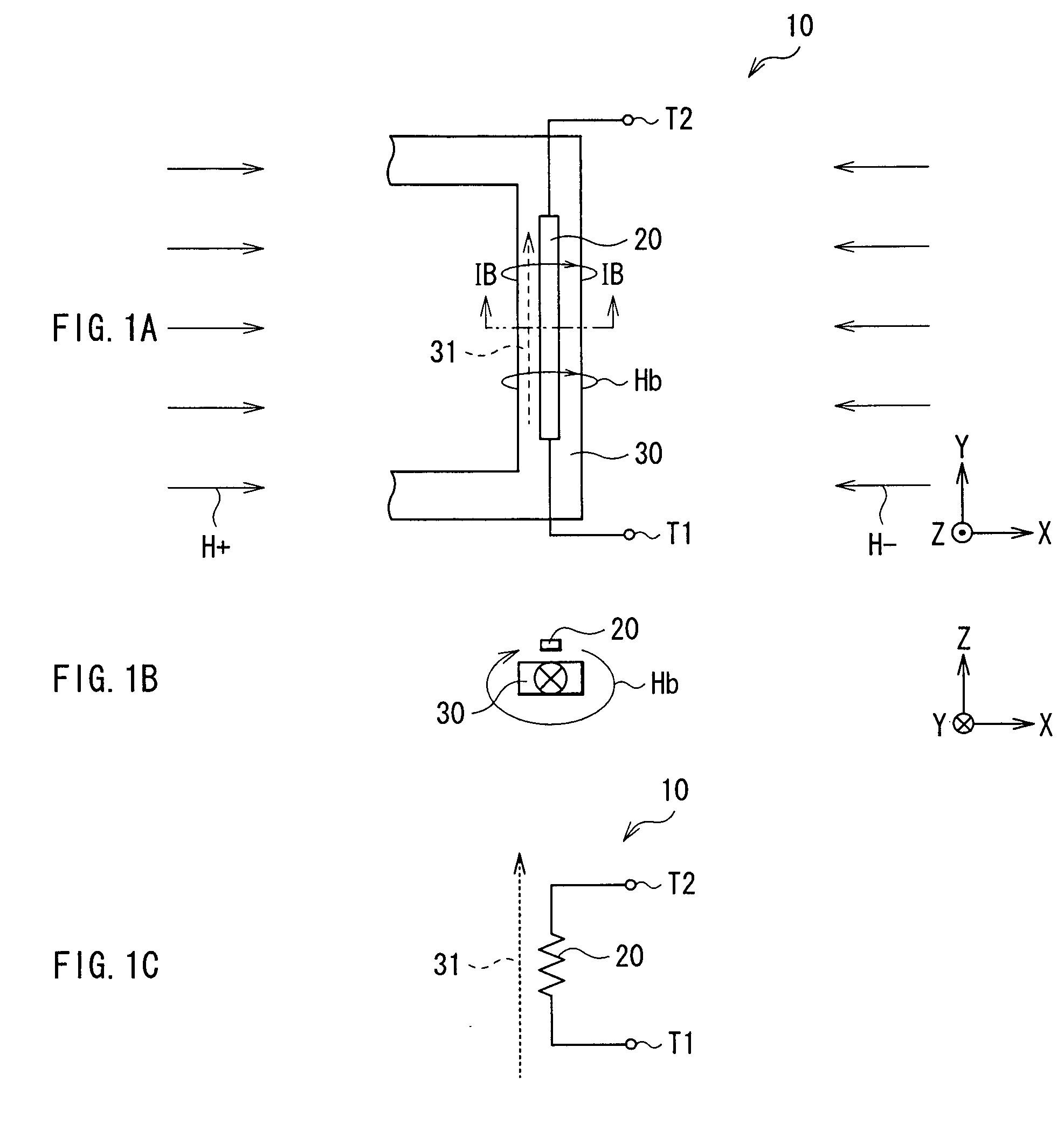
[0063]FIGS. 1A to 1C show a schematic configuration of a magnetic sensing device 10 of the first embodiment. FIG. 1A is a plan view showing the configuration of the magnetic sensing device 10 and FIG. 1B shows a sectional configuration of the magnetic sensing device 10, taken along the line IB-IB of FIG. 1A. FIG. 1C shows an equivalent circuit corresponding to FIG. 1A. The magnetic sensing device 10 senses the presence / absence of a magnetic field in the environment of the magnetic sensing device 10 (external magnetic field) and the intensity of the magnetic field.
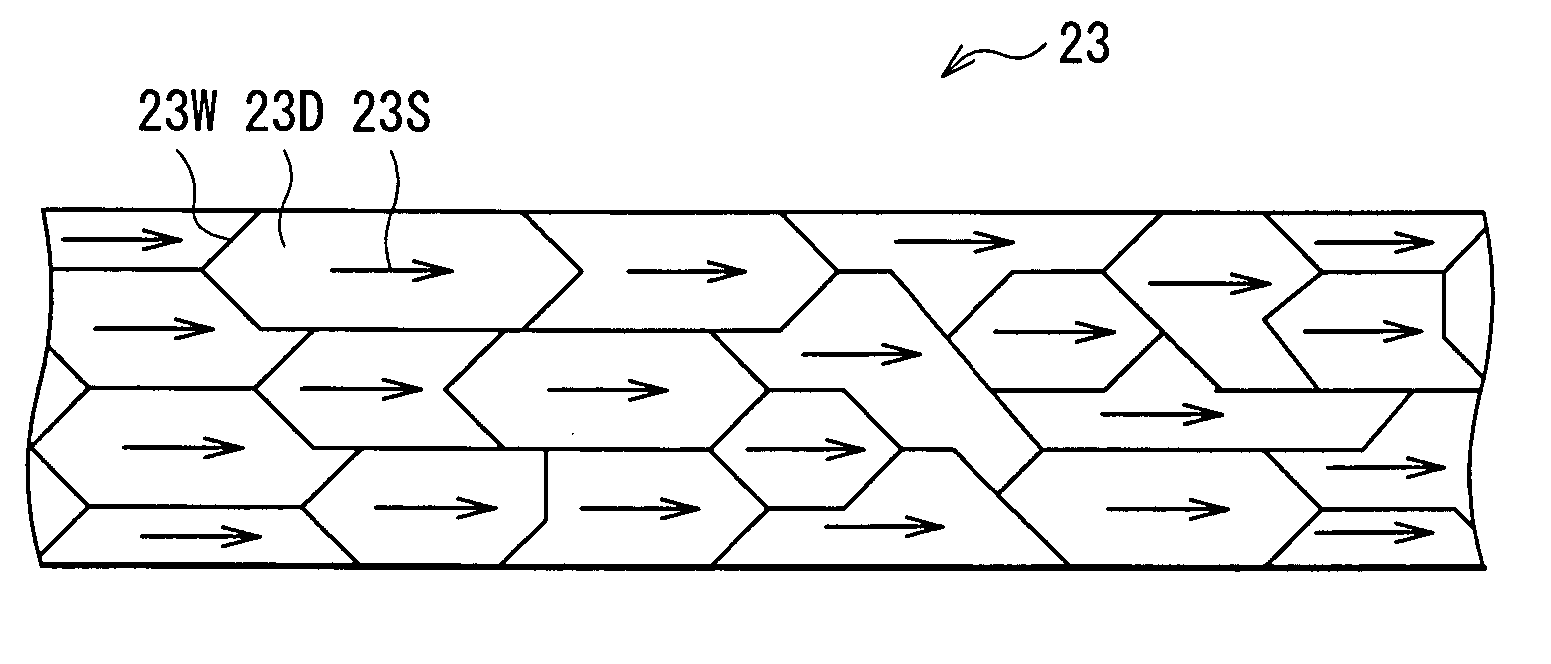
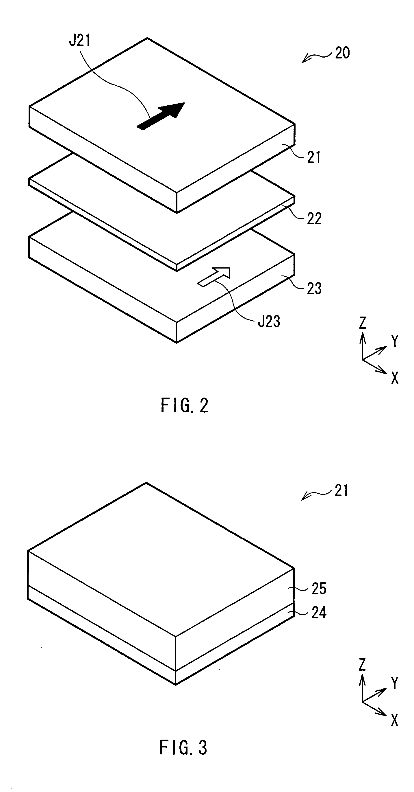
[0064] As shown in FIG. 1A, in the magnetic sensing device 10, a stacked body 20 and a bias current line 30 as bias applying means provided adjacent to the stacked body 20 are formed on a not-shown board. The stacked body 20 has a pinned layer whose magnetization ...
second embodiment
[0078] Referring now to FIG. 9, as a second embodiment of the invention, the configuration of a magnetic sensor (ammeter) using the magnetic sensing device of the invention described in the first embodiment will be described.
[0079]FIG. 9 shows a schematic configuration of a magnetic sensor 1 of the invention.
[0080] The magnetic sensor 1 shown in FIG. 9 is an ammeter for detecting a magnetic field to be sensed which is generated by current to be sensed flowing in parallel or anti-parallel to the magnetization direction of a pinned layer. The magnetic sensor 1 has a first magnetic sensing module (hereinbelow, simply called a first module) 11 constructed by first and second magnetic sensing devices 10A and 10B connected to each other at a first connection point P1 and a second magnetic sensing module (hereinbelow, simply called a second module) 12 constructed by third and fourth magnetic sensing devices 10C and 10D connected to each other at a second connection point P2. The first an...
first modification
[0092]FIG. 11 shows the configuration of a magnetic sensor 1A as a first modification. In the magnetic sensor 1A, like in the magnetic sensor 1, a bridge circuit is constructed by the first and second modules 11 and 12 formed on the same substrate (substrate 40). The magnetic sensor 1A, however, is different from the magnetic sensor 1 with respect to the point that the first and second magnetic sensing devices 10A and 10B are disposed diagonally, and the third and fourth magnetic sensing devices 10C and 10D are disposed diagonally. Specifically, the first and third magnetic sensing devices 10A and 10C are disposed on the same straight line extending in the direction corresponding to the magnetization directions J21A and J21C, and the second and fourth magnetic sensing devices 10B and 10D are disposed in the same straight line extending in the direction corresponding to the magnetization directions J21B and J21D. The relation between each stacked body 20 and the direction of each bia...
PUM
 Abstract
Description
Claims
Application Information