Shank milling cutter having a wiper radius

Inactive Publication Date: 2005-08-25
SANDVIK INTELLECTUAL PROPERTY AB
View PDF7 Cites 17 Cited by
  • Summary
  • Abstract
  • Description
  • Claims
  • Application Information

AI Technical Summary

Benefits of technology

[0016] At its side towards the major cutting edge, the minor cutting edge extends as perpendicularly as possible in relation to the axis of rotation of the milling cutter shank. In a preferred embodiment the spacing S between the center M and the axis of rotation is greater than, or equal to, D/6, preferably greater than D/4, particularly preferably greater than D/3. That measure provides a further development in the configuration of the minor cutting edge, in regard to particularly good surface machining. Tests have shown that, in principle, the spacing of the center M from the axis of rotation should be as l

Problems solved by technology

In order, however, to achieve a high level of surface quality by means of the conventional end milling cutters, the advance speed must be selected to be ve

Method used


Image

  • Shank milling cutter having a wiper radius
  • Shank milling cutter having a wiper radius
  • Shank milling cutter having a wiper radius

Examples


Embodiment Construction

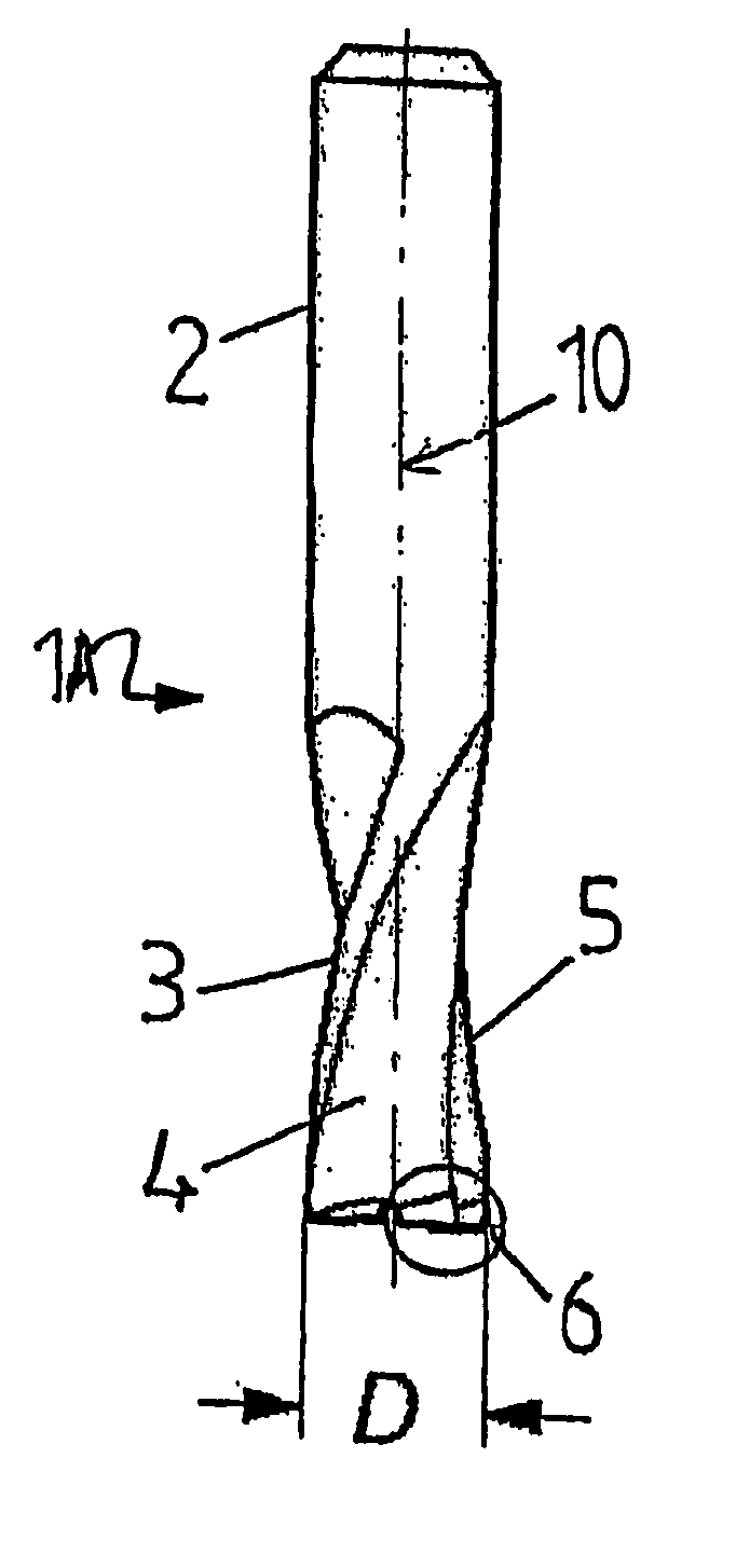
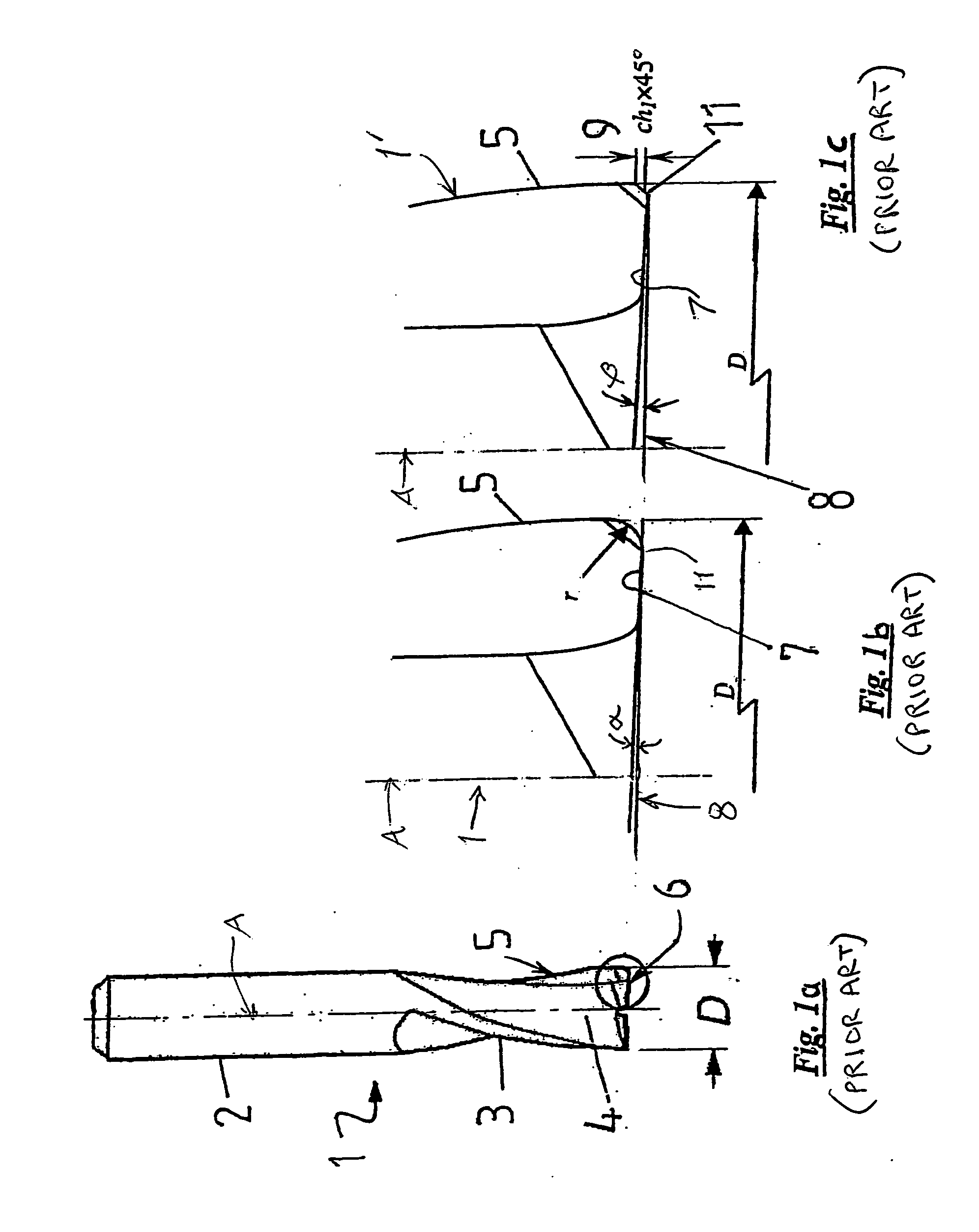
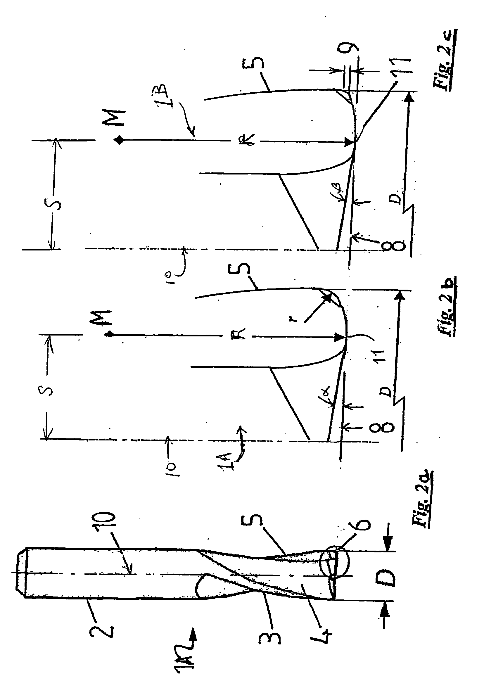
[0032]FIG. 1 a shows a side view of a prior art end shank milling cutter 1 comprising a shank portion 2 and a cutting portion 3. The shank portion 2 is here in the form of a cylindrical shank. It will be appreciated however that it is also possible to use all other shank shapes, such as for example a Morse taper shank, a steep-angle taper shank, a Weldon shank or a whistle notch shank. Here the cutting portion 3 has two major cutting edges 5 which are separated from each other by two spiral flutes 4. Peripheral surface sections of the cutting portion situated between the flutes define a cylindrical envelope surface of the cutting portion. The major cutting edges are provided at the peripheral surface of the cylindrical cutting portion 3. The end faces of the cutting portion have the minor cutting edges 7. The milling cutter has an end diameter D, as shown in FIG. 1a.

[0033]FIGS. 1b and 1c show respective configurations of a circled portion of the cutting edge corner of FIG. 1a.

[003...


PUM


Abstract

A shank milling cutter includes a cutting portion which is intended to come into engagement with the workpiece, wherein the envelope surface of the cutting portion is substantially cylindrical. At least one major cutting edge is arranged at the peripheral surface of the cutting portion and at least one minor cutting edge (face cutting edge) is arranged at the end face of the cutting portion and with an end diameter D. The minor cutting edge, in projection onto a plane containing the milling cutter axis, has a convexly curved portion with a radius of curvature R>D/2 and a center of curvature M located such that a distance from the center of curvature M to the axis is in a range from zero to a value smaller than D/2.

Description

[0001] This application is a continuation of International Application Serial No. PCT / EP03 / 05389 filed on May 23, 2003, and which claims priority of Patent Application Serial No. 102 25 481.8 filed in Germany on Jun. 10, 2002.BACKGROUND [0002] The present invention concerns a shank milling cutter preferably for performing end milling operations. [0003] Milling is a cutting machining process using a rotating tool. In that procedure the cutting edges produce the cutting movement by virtue of their rotation about the central axis of the tool. The advance movements can take place in various directions. They are effected by the tool or by the workpiece or even by both. In contrast to turning and drilling, the cutting edges are not constantly in engagement. After a cut on the workpiece they are returned in the disengaged condition to the point of first cut. As a result they can cool down and discharge the chips from the chip spaces. [0004] In principle a distinction is made between three ...

Claims


Application Information

Patent Timeline
IPC IPC(8): B23C5/10B23C5/16
CPCB23C5/10B23C2200/208B23C2210/082Y10T407/1964B23C2210/54Y10T407/1946Y10T407/1948B23C2210/084
Inventor SVENSSON, JONAS
Owner SANDVIK INTELLECTUAL PROPERTY AB
Why Eureka
Try Eureka