Fuel cell

Active Publication Date: 2005-08-25
HONDA MOTOR CO LTD
View PDF2 Cites 26 Cited by
  • Summary
  • Abstract
  • Description
  • Claims
  • Application Information

AI Technical Summary

Benefits of technology

[0012] A main object of the present invention is to provide a fuel cell with a simple structure in which the required cross secti

Problems solved by technology

However, it has been found that it is not possible to produce a thin separator using the carbon material due t

Method used


Image

  • Fuel cell
  • Fuel cell
  • Fuel cell

Examples


Example

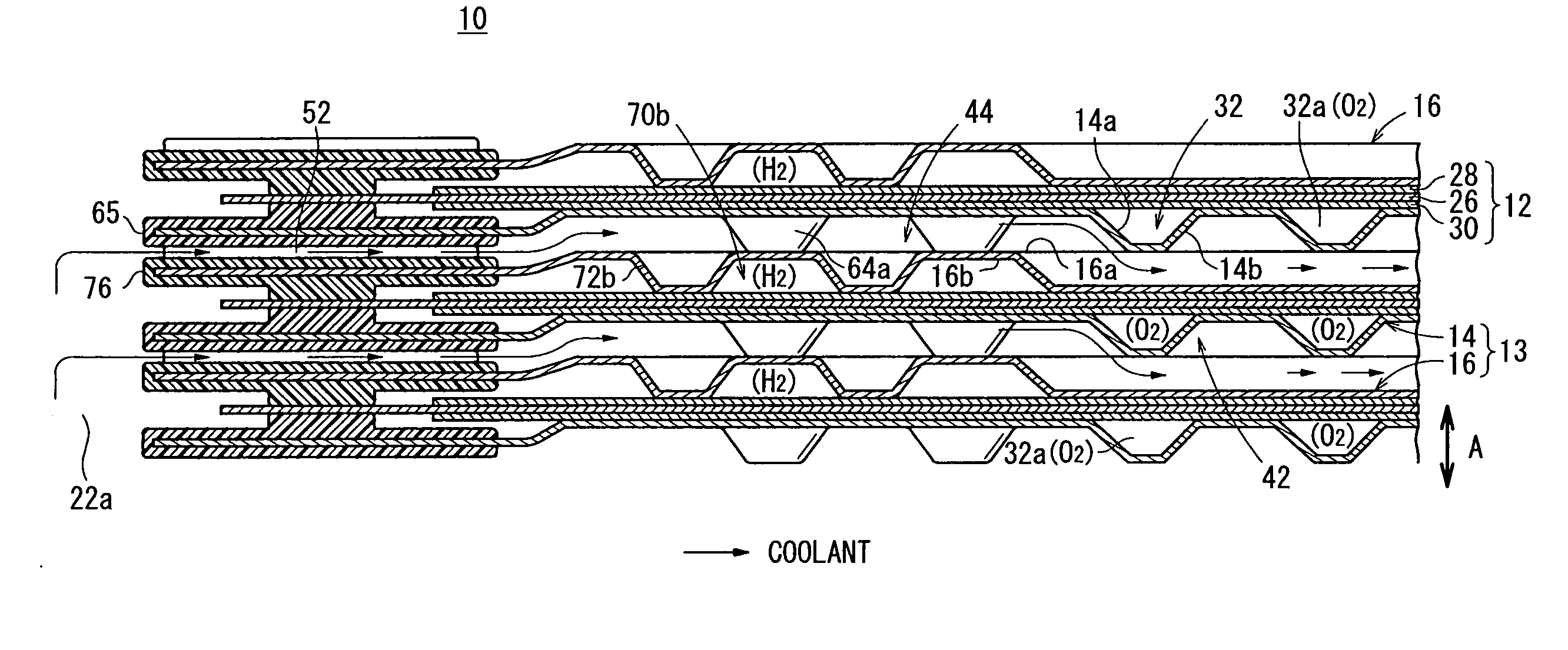
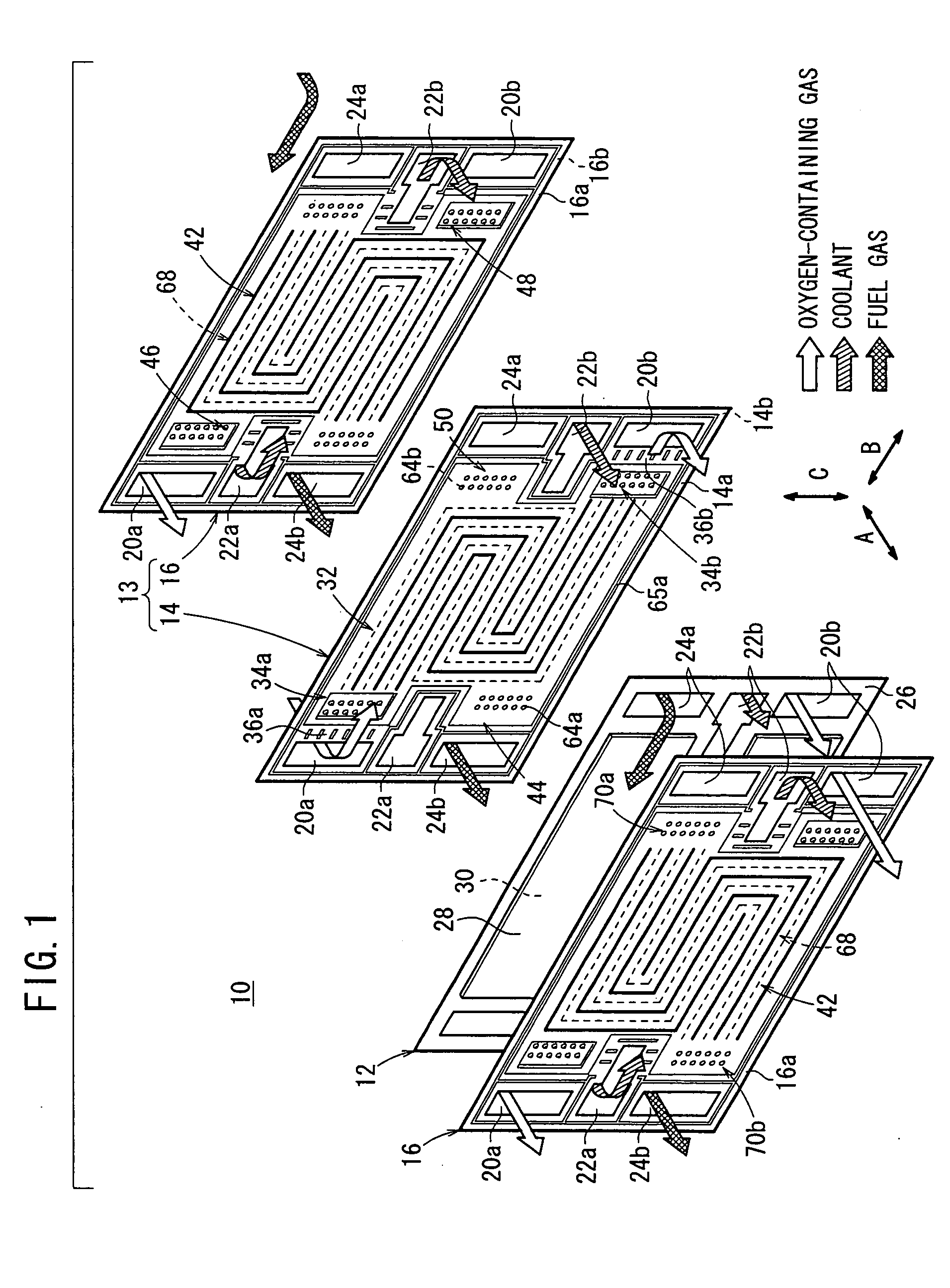
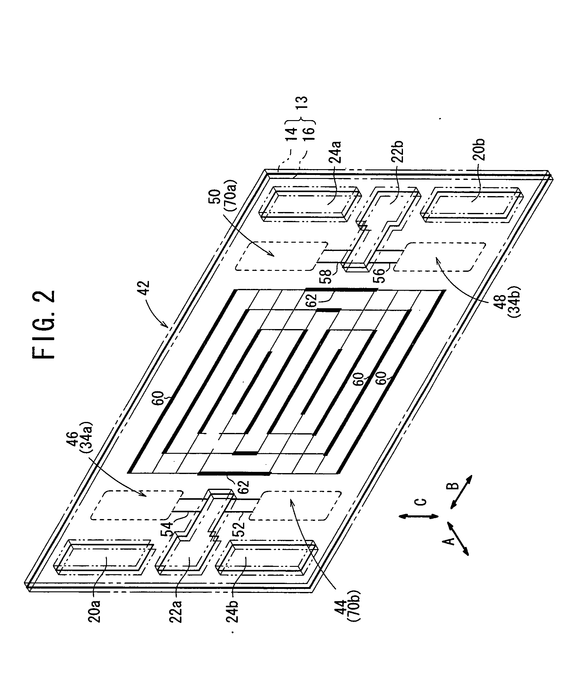
[0035]FIG. 1 is an exploded perspective view showing main components of a fuel cell 10 according an embodiment of the present invention. FIG. 2 is a perspective view showing a coolant flow field 42 (described later) of the fuel cell 10. FIG. 3 is a front view showing the coolant flow field 42.

[0036] The fuel cell 10 is formed by stacking a membrane electrode assembly (MEA) 12 and separators 13 alternately. Each of the separators 13 includes first and second metal plates 14, 16 which are stacked together (see FIGS. 1, 4 to 7). The separator 13 may include, e.g., three metal plates.

[0037] As shown in FIG. 1, at one end of the fuel cell 10 in a direction indicated by an arrow B, an oxygen-containing gas supply passage 20a for supplying an oxygen-containing gas, a coolant supply passage 22a for supplying a coolant, and a fuel gas discharge passage 24b for discharging a fuel gas such as a hydrogen-containing gas are arranged vertically in a direction indicated by an arrow C. The oxygen...


PUM


Abstract

A fuel cell includes a membrane electrode assembly and separators sandwiching the membrane electrode assembly. Each of the separators includes first and second metal plates. When the fist and second metal plates are stacked together, an inlet buffer and an outlet buffer are overlapped with each other in the stacking direction. A plurality of bosses in the inlet buffer and a plurality of bosses in the outlet buffer are not overlapped with each other.

Description

BACKGROUND OF THE INVENTION [0001] 1. Field of the Invention [0002] The present invention relates to a fuel cell formed by stacking an electrolyte electrode assembly and separators alternately in a stacking direction. The electrolyte electrode assembly includes a pair of electrodes and an electrolyte interposed between the electrodes. Reactant gas passages and coolant passages extend through the fuel cell in the stacking direction. [0003] 2. Description of the Related Art [0004] For example, a solid polymer electrolyte fuel cell employs a polymer ion exchange membrane as a solid polymer electrolyte membrane. The solid polymer electrolyte membrane is interposed between an anode and a cathode to form a membrane electrode assembly. Each of the anode and the cathode is made of electrode catalyst and porous carbon. The membrane electrode assembly is sandwiched between separators (bipolar plates) to form the fuel cell. In use, generally, a predetermined number of the fuel cells are stacke...

Claims


Application Information

Patent Timeline
IPC IPC(8): H01M8/04H01M8/10H01M8/02H01M8/24
CPCH01M8/0258H01M8/0267Y02E60/50H01M8/248H01M8/241H01M8/2483H01M8/0263
Inventor SUGIURA, SEIJIGOTO, SHUHEI
Owner HONDA MOTOR CO LTD
Why Eureka
Try Eureka