Load-lock technique

a technology of loading and releasing, applied in the field of loading locks, can solve the problems of reducing the time required for the process itself, affecting the production yield, and affecting the quality of the product, so as to reduce or suppress the contamination or temperature drop

Inactive Publication Date: 2005-08-25
CANON KK
View PDF11 Cites 50 Cited by
  • Summary
  • Abstract
  • Description
  • Claims
  • Application Information

AI Technical Summary

Benefits of technology

[0015] It is accordingly an object of the present invention to provide load-lock technique by which high-speed vacuum exhausting is enabled while reducing or suppressing contamination or temperature decrease of an object to be loaded and / or unloaded.
[0017] In accordance with another aspect of the present invention, there is provided a load-lock method, comprising the steps of: conveying an object into a chamber housing; reducing the capacity of the chamber housing after said conveying step; and reducing the pressure inside the chamber housing after said capacity reducing step.
[0018] Briefly, in accordance with the present invention, load-lock technique by which high-speed pressure reduction is enabled while suppressing contamination or temperature decrease of an object to be loaded and / or unloaded, can be provided.

Problems solved by technology

However, in the load-lock chamber structure such as described above, when the gas is exhausted to create a vacuum level in place of the atmospheric pressure state, at the moment as the exhaust valve is opened the atmospheric air inside the chamber is exhausted rapidly.
As a result of this, the moisture content contained in the atmosphere is frozen and adhered to the substrate surface, causing contamination of it.
Such temperature rise is a serious factor for slowing down the production yield, particularly in a process (such as lithographic process) where precise temperature control is required.
Load-lock systems are incorporated into process machines such as film forming apparatus and, in such machines, the time required for the process itself is relatively long.
If the load-lock structure is arranged for slow exhausting, although the inconveniences such as substrate contamination or temperature decrease could be avoided thereby, it needs a very long time for substrate loading and unloading.
This is a serious factor for throughput decrease of the apparatus.
Practically, therefore, the load-lock structure such as described above can not be applied to a machine such as EUV exposure apparatus in which a large throughput is required.

Method used


Image

  • Load-lock technique
  • Load-lock technique
  • Load-lock technique

Examples


embodiment 1

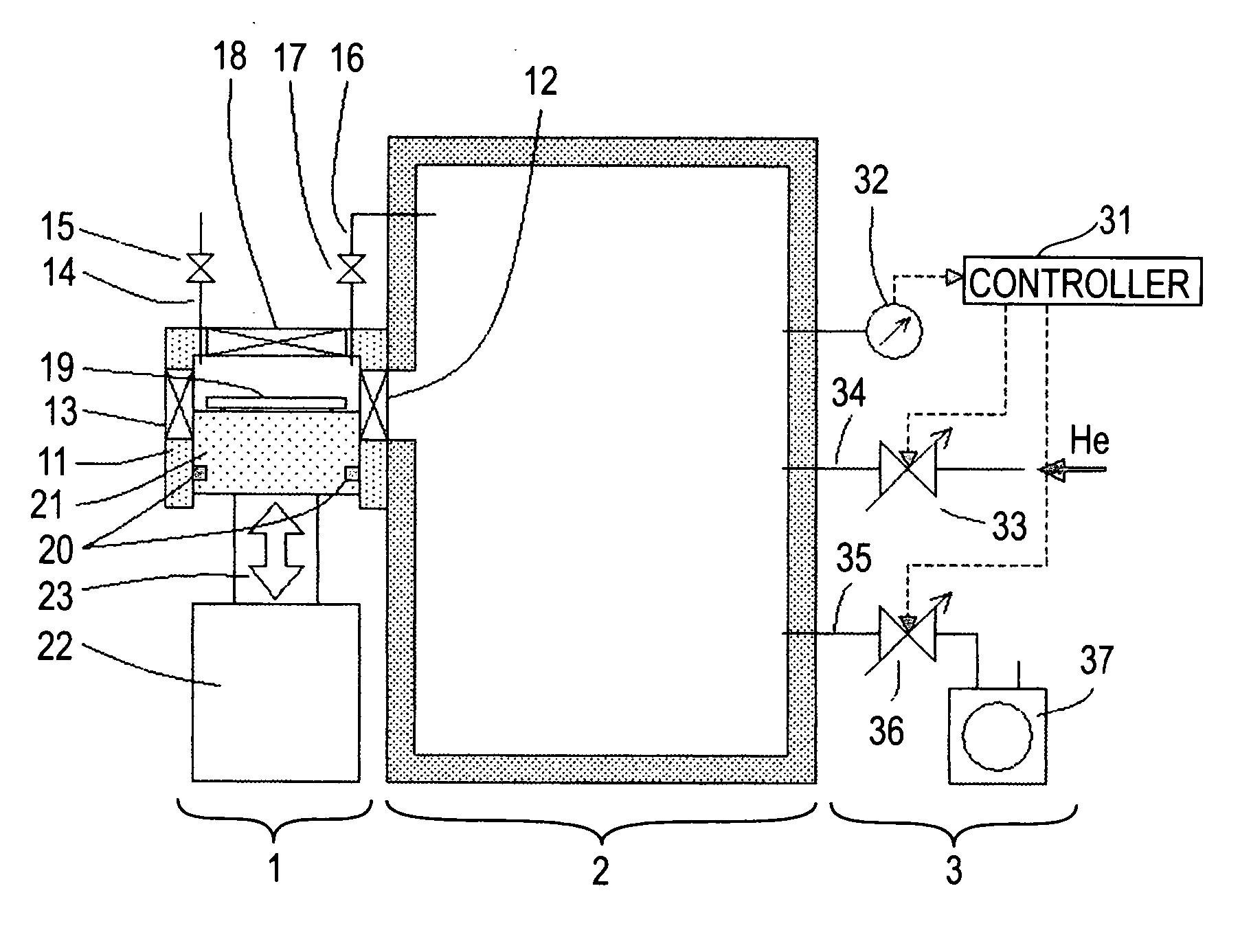
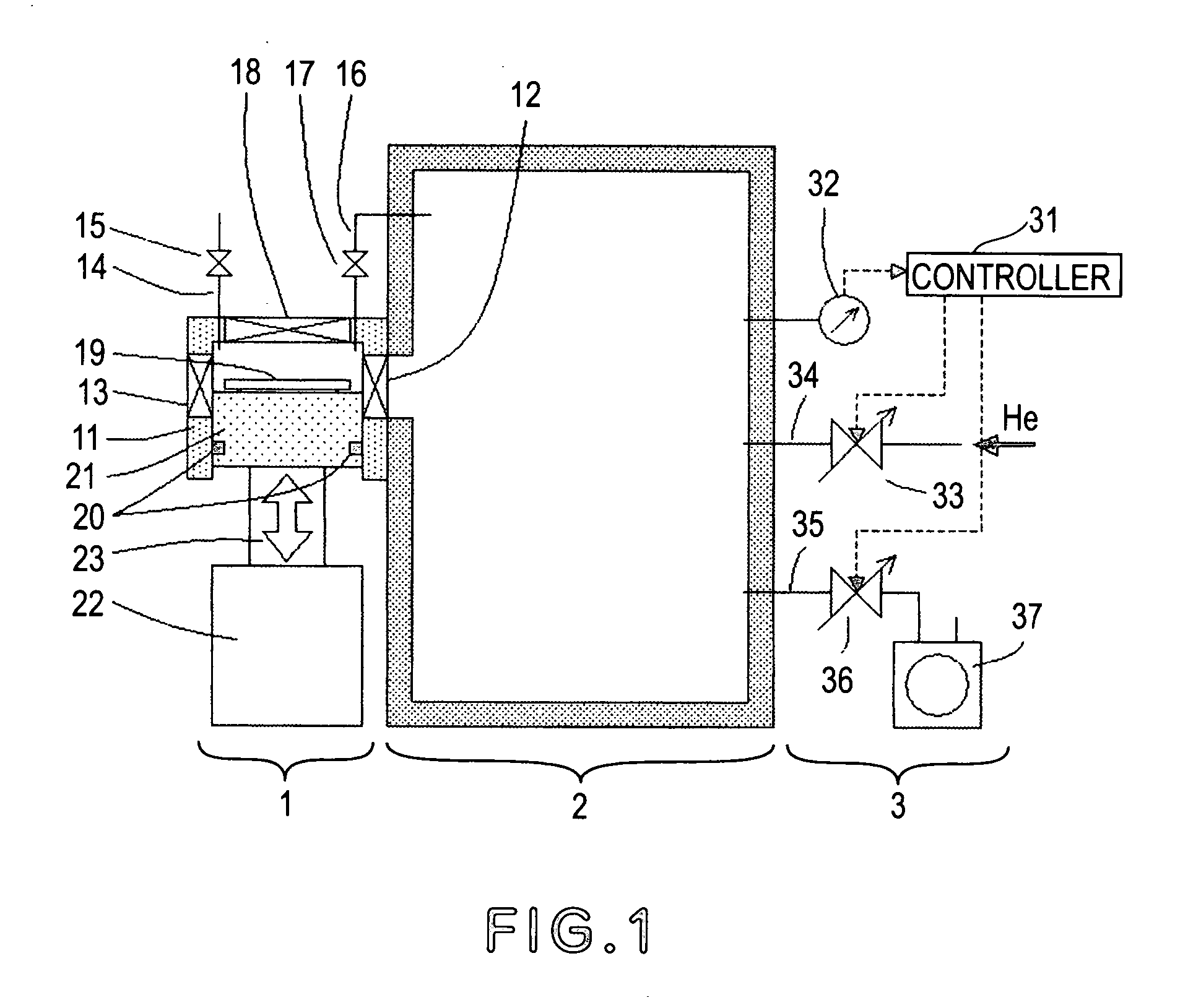
[0051]FIG. 1 illustrates a load-lock system according to a first embodiment of the present invention. In this embodiment, the invention is applied to an X-ray exposure apparatus in which the exposure process is carried out in a particular ambience such as reduced pressure He ambience, for example. Denoted at 1 is a load-lock system of the present invention. The load-lock system 1 is provided to load a substrate 19 into a main chamber 2 from the atmosphere and also to unload the substrate 19, after an exposure process is carried out thereto inside the main chamber 2, outwardly (to the atmosphere), without breaking a particular ambience of the main chamber 2 such as reduced pressure He ambience, for example. Denoted at 2 is the main chamber in which a process (e.g., exposure process in this embodiment) is to be carried out to the substrate 19 in a particular ambience. Inside the main chamber 2, there are components for carrying out an exposure process to the substrate 19, such as a co...

embodiment 2

[0077]FIG. 4 illustrates a load-lock system according to a second embodiment of the present invention. In this embodiment, the invention is applied to an EUV exposure apparatus in which the exposure process is carried out in a vacuum ambience. In this embodiment, components having corresponding functions as of those of the first embodiment are denoted by like numerals, and detailed description for them will be omitted.

[0078] Denoted at 1 is a load-lock system of the present invention. The load-lock system 1 is provided to load a substrate 19 into a main chamber 2 from the atmosphere and also to unload the substrate, after an exposure process is carried out thereto inside the main chamber 2, outwardly (to the atmosphere), without breaking a vacuum ambience of the main chamber 2. Denoted at 2 is the main chamber which is normally exhausted by means of a vacuum pump, and a vacuum level is maintained therein. Inside the main chamber 2, there are components for carrying out an exposure ...

embodiment 3

[0164]FIGS. 10A and 10B show a third embodiment of the present invention. In this embodiment, the invention is applied to an exposure apparatus. It comprises a process chamber 1 that accommodates therein a wafer exposure process unit, not shown, and a reduced pressure He ambience is created and kept therein. The apparatus further comprises a wafer carrier (wafer supply unit) 3 which is disposed in the atmosphere. In this embodiment, the wafer carrier 3 is a FOUP system. A chamber auxiliary room 2 is connected to the process chamber 1, and second conveying means 52 to be described later is disposed in this chamber auxiliary room 2.

[0165] Disposed between the chamber auxiliary room 2 and the wafer supply unit 3 is a load-lock chamber 4 for allowing transfer of a wafer between difference ambiences. The load-lock chamber 4 is communicated with the atmosphere and the chamber auxiliary room 2, respectively, through a first gate valve 41 and a second gate valve 42, respectively.

[0166] At...


PUM

PropertyMeasurementUnit
wavelengthaaaaaaaaaa

Abstract

Disclosed is a load-lock system, an exposure apparatus having the same, and a load-lock method. In one preferred form, the load-lock system includes a chamber housing, and a capacity changing system for changing the capacity of the chamber housing. The load-lock method includes the steps of conveying an object into a chamber housing, reducing the capacity of the chamber housing after the conveying step, and reducing the pressure inside the chamber housing after the capacity reducing step.

Description

FIELD OF THE INVENTION AND RELATED ART [0001] This invention relates to load-lock technique applicable to production of various microdevices such as, for example, semiconductor chips (e.g., IC or LSI), display devices (e.g., liquid crystal panel), detecting elements (e.g., magnetic head), and image pickup devices (e.g., CCD). [0002] The density and speed of a semiconductor integrated circuit have been improved significantly and, with this trend, the linewidth of an integrated circuit pattern has been narrowed more and more. This forces further improvements in the semiconductor manufacturing method. As regards exposure apparatuses used for forming a resist pattern in a lithographic process which is one of semiconductor manufacturing processes, those using deep ultraviolet light such as KrF laser light (wavelength 248 nm), ArF laser light (wavelength 193 nm) or F2 laser light (wavelength 157 nm) have been developed. Currently, EUV exposure apparatuses that use extreme ultraviolet ligh...

Claims


Application Information

Patent Timeline
Patent Type & Authority Applications(United States)
IPC IPC(8): B65G49/00G03F7/20H01L21/027H01L21/00H01L21/677
CPCH01L21/67751H01L21/67201G03F7/70841
Inventor KASUMI, KAZUYUKI
Owner CANON KK
Why Eureka
Try Eureka