Microengineered broadband electrical switches

a broadband, electrical switch technology, applied in the field of low loss electrical switches, can solve the problems of high impedance between the signal lines, and achieve the effect of high level of electrical isolation

Inactive Publication Date: 2005-09-01
MICROSAIC SYST
View PDF5 Cites 37 Cited by
  • Summary
  • Abstract
  • Description
  • Claims
  • Application Information

AI Technical Summary

Benefits of technology

[0009] Accordingly, the present invention provides an electrically controlled micro-mechanical switch, suitable for fabrication by MEMS technology, for use in switching low frequency or radio frequency (RF) signals over a wide frequency range. In accordance with the invention, a laterally actuated micro-electromechanical switch is provided which is suitable for thermal actuation, and suitable for high and low frequency signals, in which the control and signal circuits are well isolated from each other. The invention achieves switching by use of a bridging element which is held in position by latch mechanisms. The bridging element or switching member is supported on a cantilevered beam wh

Problems solved by technology

When they are in their relaxed state, these structures are not in electrical or mechanical contact

Method used


Image

  • Microengineered broadband electrical switches
  • Microengineered broadband electrical switches
  • Microengineered broadband electrical switches

Examples


Embodiment Construction

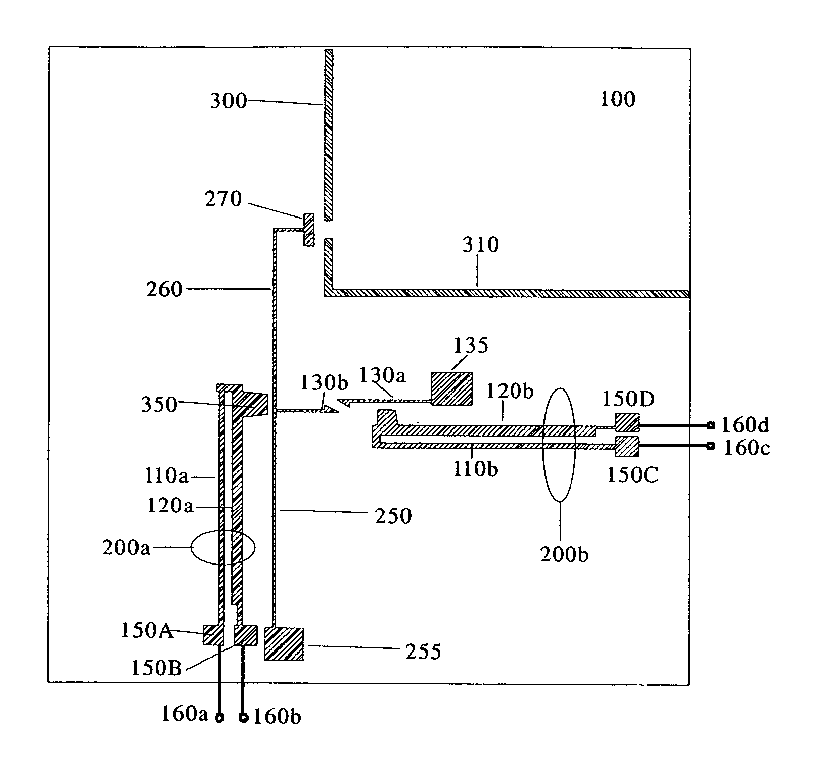
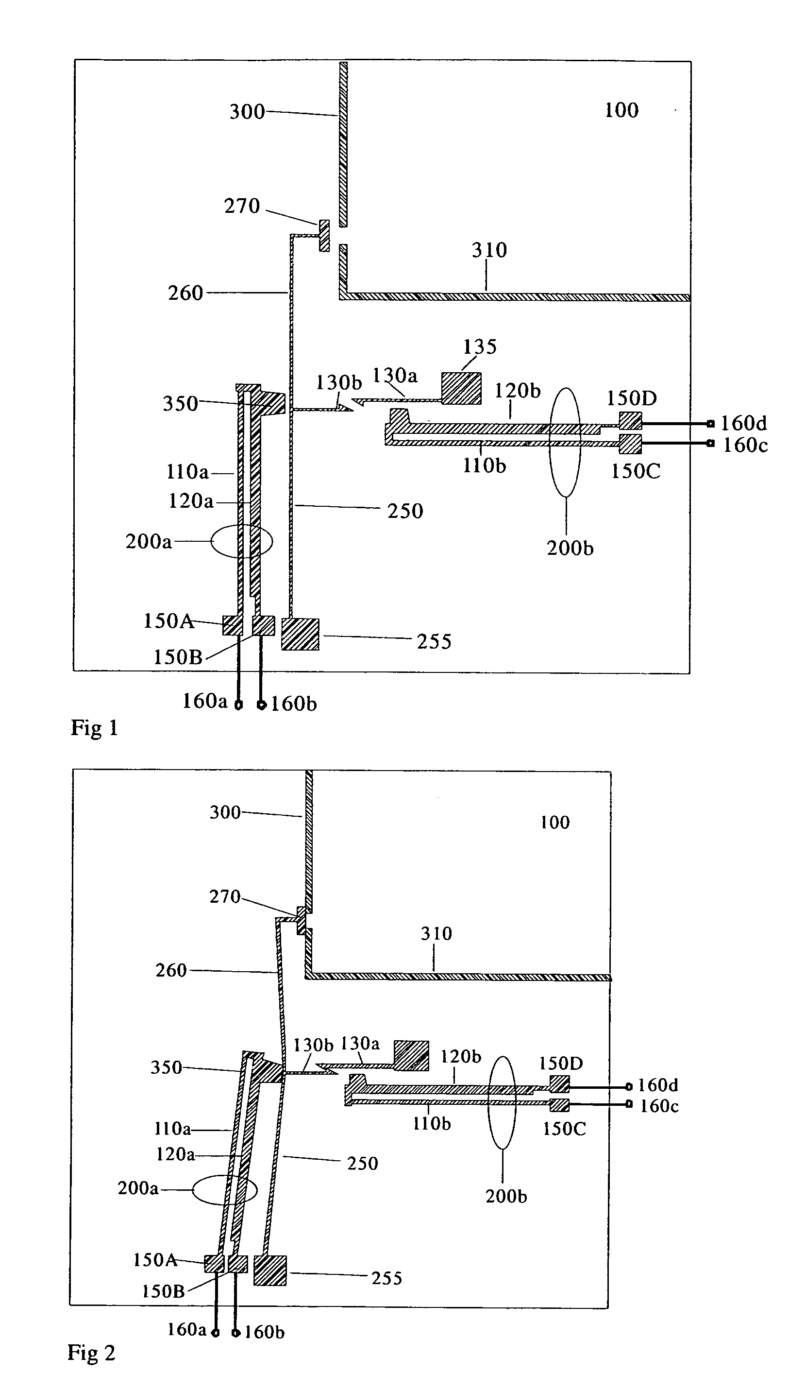
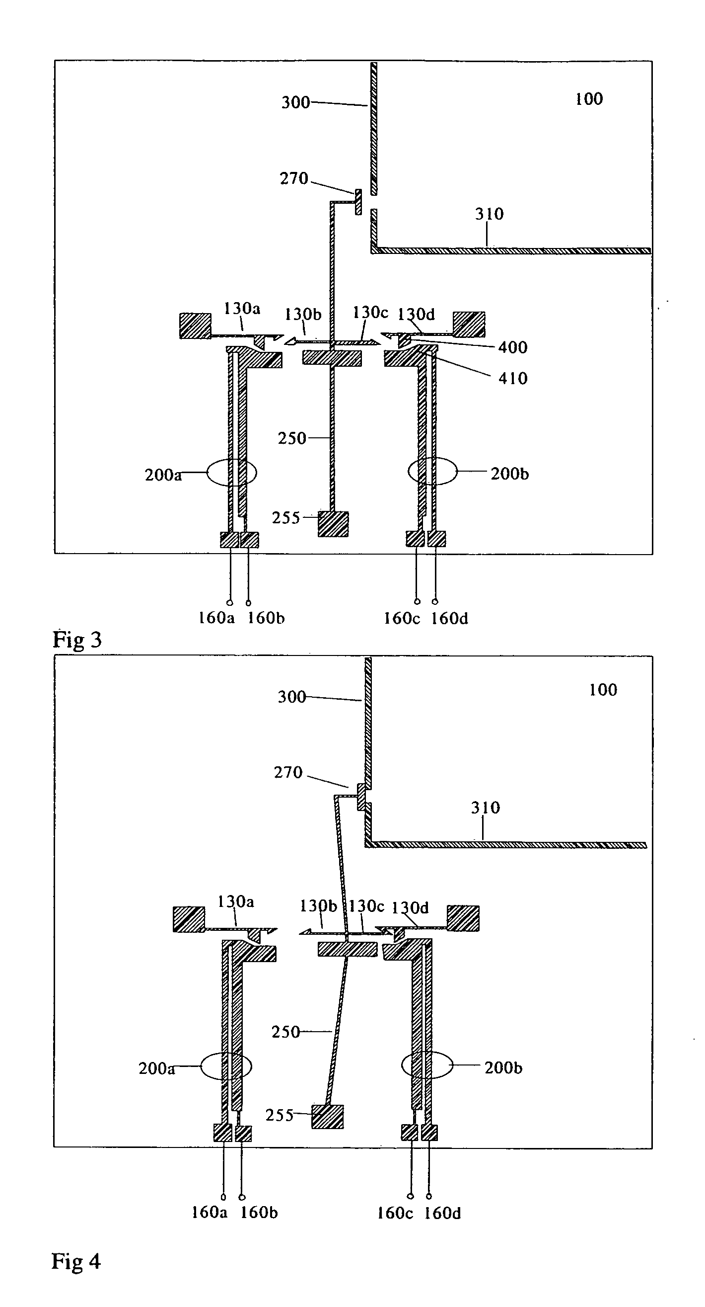
[0026] Referring in detail to the drawings where similar parts are identified by like reference numbers, there is seen in FIGS. 1 and 2 a diagram of a single pole single throw RF MEMS switch, in accordance with the present invention, in its open and closed position respectively. The switch is provided on a substrate 100 and is mounted in such a way as to present a number of electrical terminals 160 for connection to a printed circuit board or otherwise for connection to external control circuits. Terminals 160a and 160b provide the connections for passing an actuation current through a first actuator formed as a cantilever 200a. Each external terminal 160 is electrically connected, for example by wire bonding, to a fixed anchor 150, each anchor being a part mechanically fixed to, but electrically isolated from, the substrate. The substrate may be a silicon wafer, or some other planar substrate suitable for processing with semiconductor process equipment such as photolithography tool...


PUM


Abstract

A MEMS switching device including a first and second actuator and a switching member is described, the switching member being adapted to selectively provide a signal path between a first and second signal line. The selective provision of the signal path is effected by movement of a switching member from a first position to a second position, the movement of the switching member being effected by action of the first and second actuators thereon, such action resulting from a deformation of the actuators. In one embodiment of the invention, catch mechanisms link the switching member to the substrate in a first position, such that the switching member is maintained in this position when the actuation force is removed, and can be released by deformation of one actuator. In another embodiment of the invention, catch mechanisms are provided to maintain the switching member in each of two positions, and single actuators for each of the two positions provide both release of the catch mechanism for that position and translation of the switching member to the other position. In each embodiment, actuators are electrically disconnected from the switching elements other than during change of the switch position, so that interference between the switched signal path and the control circuits is avoided.

Description

FIELD OF THE INVENTION [0001] The invention relates to switches and in particular to switches applied or manufactured using micro-electro-mechanical systems (MEMS) technology. More particularly the invention relates to low loss electrical switches. BACKGROUND OF THE INVENTION [0002] One of the expanding applications of micro-electro-mechanical systems (MEMS) technology is in the area of low loss electrical switches. These switches are essentially miniaturised electromechanical switches or relays, and can be utilised to switch signals with frequencies from DC to above 40 GHz rapidly, efficiently and with minimal loss. The main alternative approach for highly miniaturised electrical switching is the use of solid-state technology. This relies on diodes or MESFETs which typically incur a 1 to 2 dB loss per switch depending on frequency and also, particularly in the case of diodes, have a high power consumption. MEMS switches typically exhibit low signal losses, and the power required to...

Claims


Application Information

Patent Timeline
IPC IPC(8): H01H1/00H01H37/00H01H57/00H01H59/00
CPCH01H1/0036H01H2037/008H01H2001/0047H01H37/00
Inventor YEATMAN, ERICSYMS, RICHARD
Owner MICROSAIC SYST
Why Eureka
Try Eureka