Microfluidic devices for electrophoretic analysis of materials
Inactive Publication Date: 2005-09-01
CAPLIPER LIFE SCI INC
View PDF30 Cites 22 Cited by
Summary
Abstract
Description
Claims
Application Information
AI Technical Summary
This helps you quickly interpret patents by identifying the three key elements:
Problems solved by technology
Method used
Benefits of technology
[0007] The present invention provides for a microfluidic system for high-speed electrophoretic analysis of subject materials for applications in the fields of chemistry, biochemistry, biotechnology, molecular biology and numerous other areas. The system has a channel in a substrate, a light source and a photoreceptor. The channel holds subject materials in solution in an electric field so that the materials move through the channel and separate into bands according to species. The light source excites fluoresc
Problems solved by technology
While these operations are fast compared to macroscale electrophoretic methods, the operations fall short of a hi
Method used
Image
Click on the blue label to locate the original text in one second.
Reading with bidirectional positioning of images and text.
Examples
Embodiment Construction
[0014] General Description of Microfluidic Systems
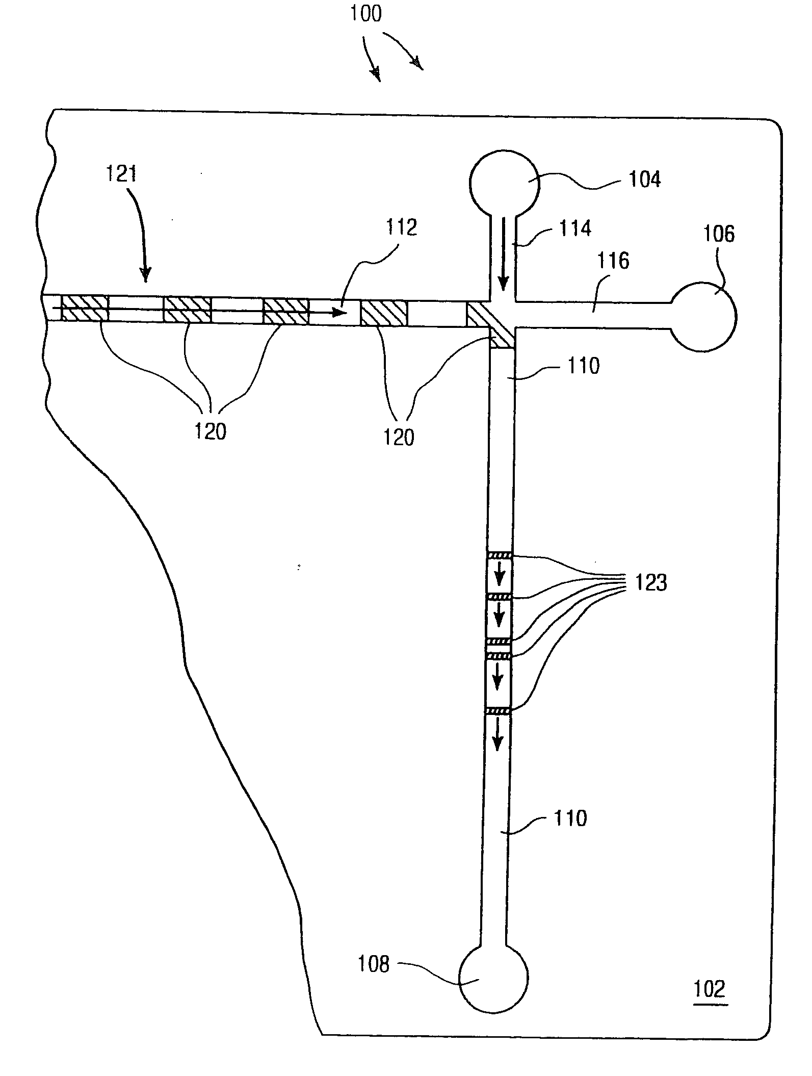
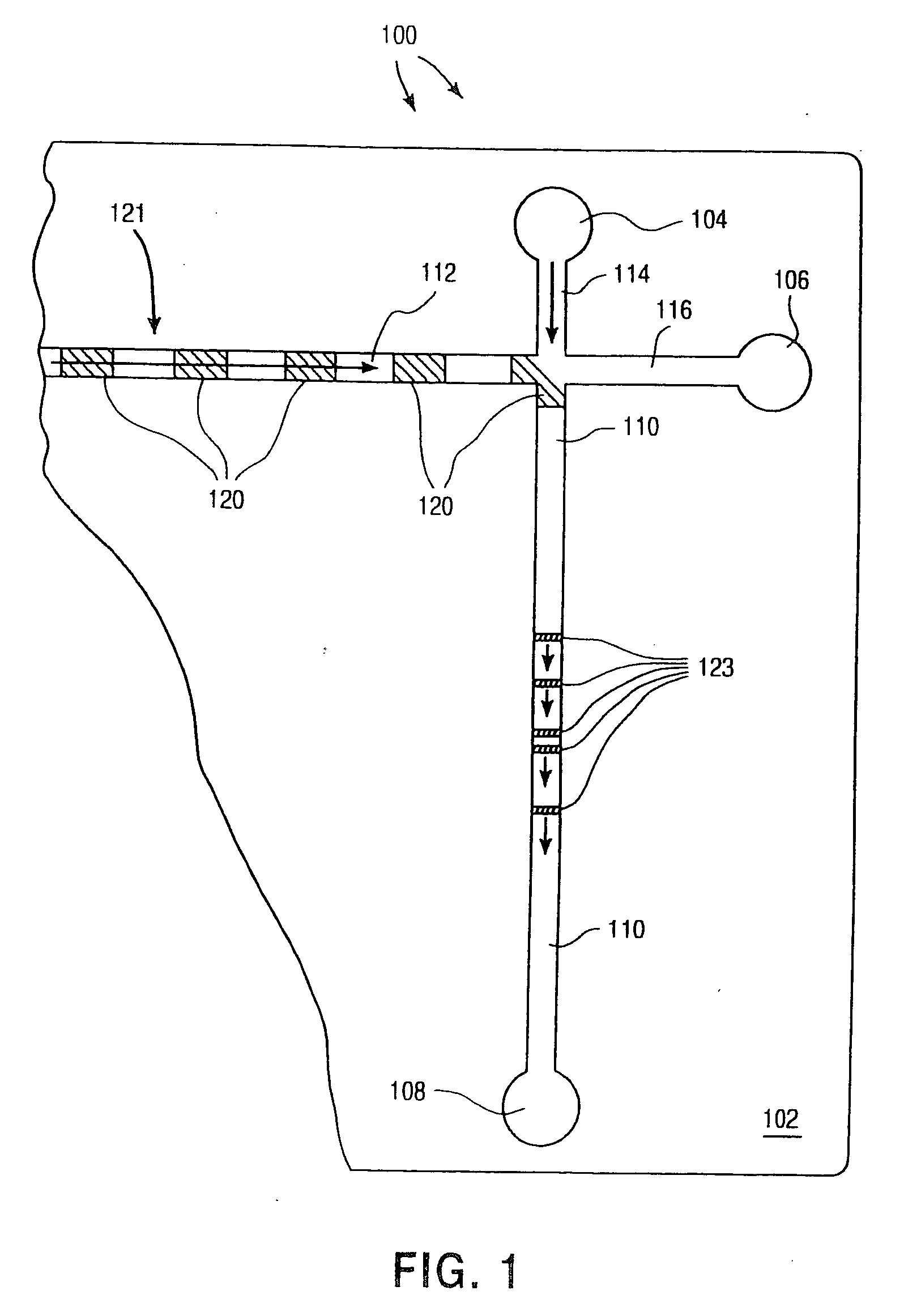
[0015]FIG. 1 discloses a representative diagram of an exemplary microfluidic system 100 according to the present invention. As shown, the overall device 100 is fabricated in a planar substrate 102. Suitable substrate materials are generally selected based upon their compatibility with the conditions present in the particular operation to be performed by the device. Such conditions can include extremes of pH, temperature, salt concentration, and application of electrical fields. Additionally, substrate materials are also selected for their inertness to critical components of an analysis or synthesis to be carried out by the system.
[0016] Useful substrate materials include, e.g., glass, quartz and silicon, as well as polymeric substrates, e.g., plastics. In the case of conductive or semiconductive substrates, there should be an insulating layer on the substrate. This is particularly important where the device incorporates electrical ...
PUM
Property
Measurement
Unit
Force
aaaaa
aaaaa
Pressure
aaaaa
aaaaa
Electric potential / voltage
aaaaa
aaaaa
Abstract
The present invention provides a microfluidic system for fast, accurate and low cost electrophoretic analysis of materials in the fields of chemistry, biochemistry, biotechnology, molecular biology and numerous other fields. Light from periodically spaced regions along a channel in the microfluidic system are received by a photodetector. The intensity of light received by the photodetector is modulated by the movement of species bands through the channel under electrophoretic forces. By Fourier analysis, the velocity of each species band is determined and the identification of the species is made by its electrophoretic mobility in the channel.
Description
CROSS-REFERENCE TO RELATED APPLICATIONS [0001] This application is a continuation of U.S. patent application Ser. No. 09 / 977,056 filed Oct. 12, 2001, which is a continuation of U.S. patent application Ser. No. 09 / 378,169 filed Aug. 19, 1999 (now U.S. Pat. No. 6,337,740), which is a continuation of U.S. patent application Ser. No. 09 / 207,864 filed Dec. 8, 1998 (now U.S. Pat. No. 6,233,048), which is a continuation of U.S. patent application Ser. No. 08 / 941,679 filed Sep. 30, 1997 (now U.S. Pat. No. 5,852,495), which is a continuation of U.S. patent application Ser. No. 08 / 683,080 filed Jul. 16, 1996 (now U.S. Pat. No. 5,699,157).BACKGROUND OF THE INVENTION [0002] There has been a growing interest in the manufacture and use of microfluidic systems for the acquisition of chemical and biochemical information. Techniques commonly associated with the semiconductor electronics industry, such as photolithography, wet chemical etching, etc., are used in the fabrication of these microfluidic ...
Claims
Application Information
Patent Timeline
Application Date:The date an application was filed.
Publication Date:The date a patent or application was officially published.
First Publication Date:The earliest publication date of a patent with the same application number.
Issue Date:Publication date of the patent grant document.
PCT Entry Date:The Entry date of PCT National Phase.
Estimated Expiry Date:The statutory expiry date of a patent right according to the Patent Law, and it is the longest term of protection that the patent right can achieve without the termination of the patent right due to other reasons(Term extension factor has been taken into account ).
Invalid Date:Actual expiry date is based on effective date or publication date of legal transaction data of invalid patent.