Power supply unit and portable apparatus using the same
a power supply unit and portable technology, applied in emergency power supply arrangements, process and machine control, instruments, etc., can solve the problems of low overall power conversion efficiency, low power conversion efficiency of regulators, and large power consumption rate of themselves, and achieve smooth switching and high power conversion efficiency
- Summary
- Abstract
- Description
- Claims
- Application Information
AI Technical Summary
Benefits of technology
Problems solved by technology
Method used
Image
Examples
first embodiment
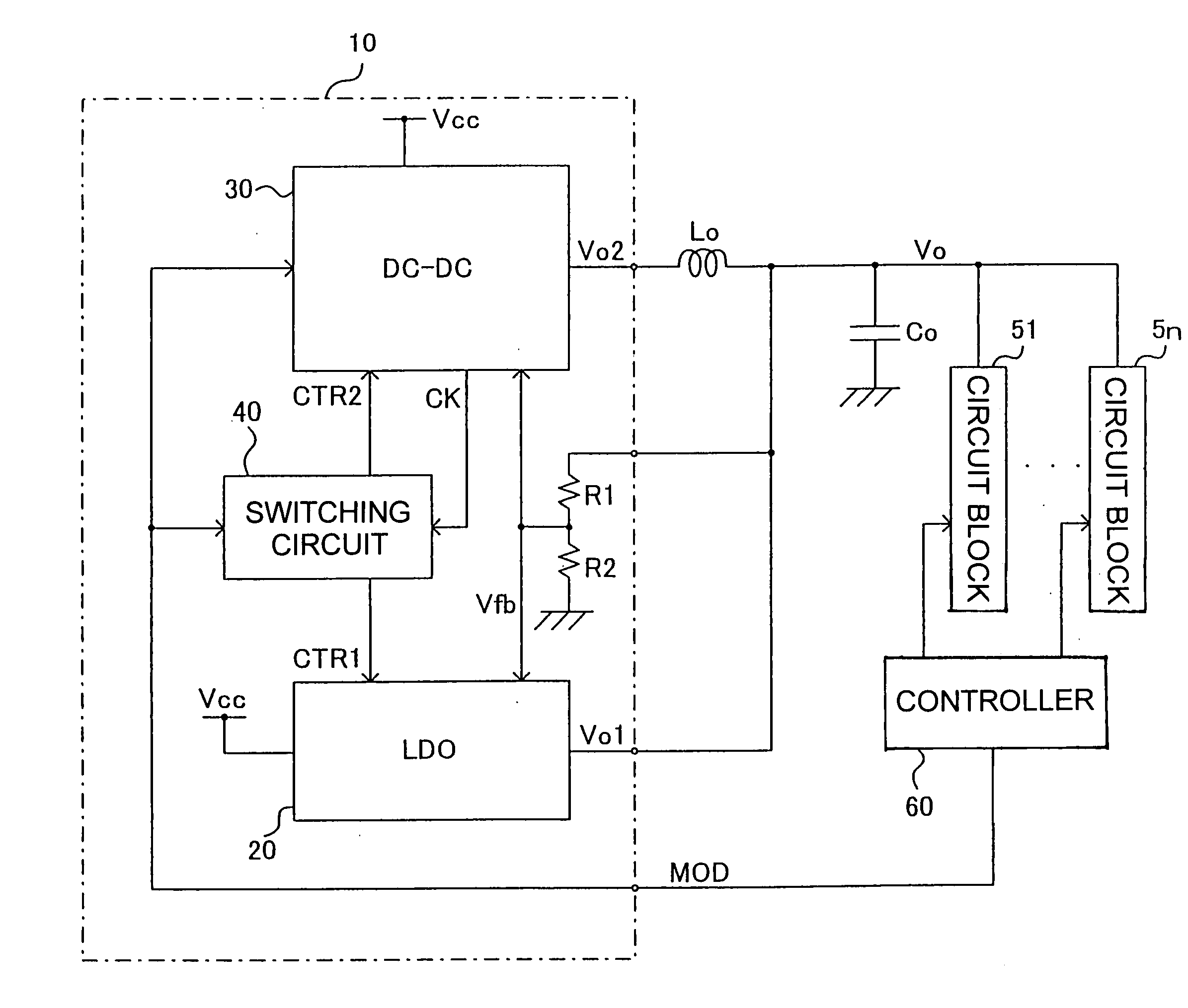
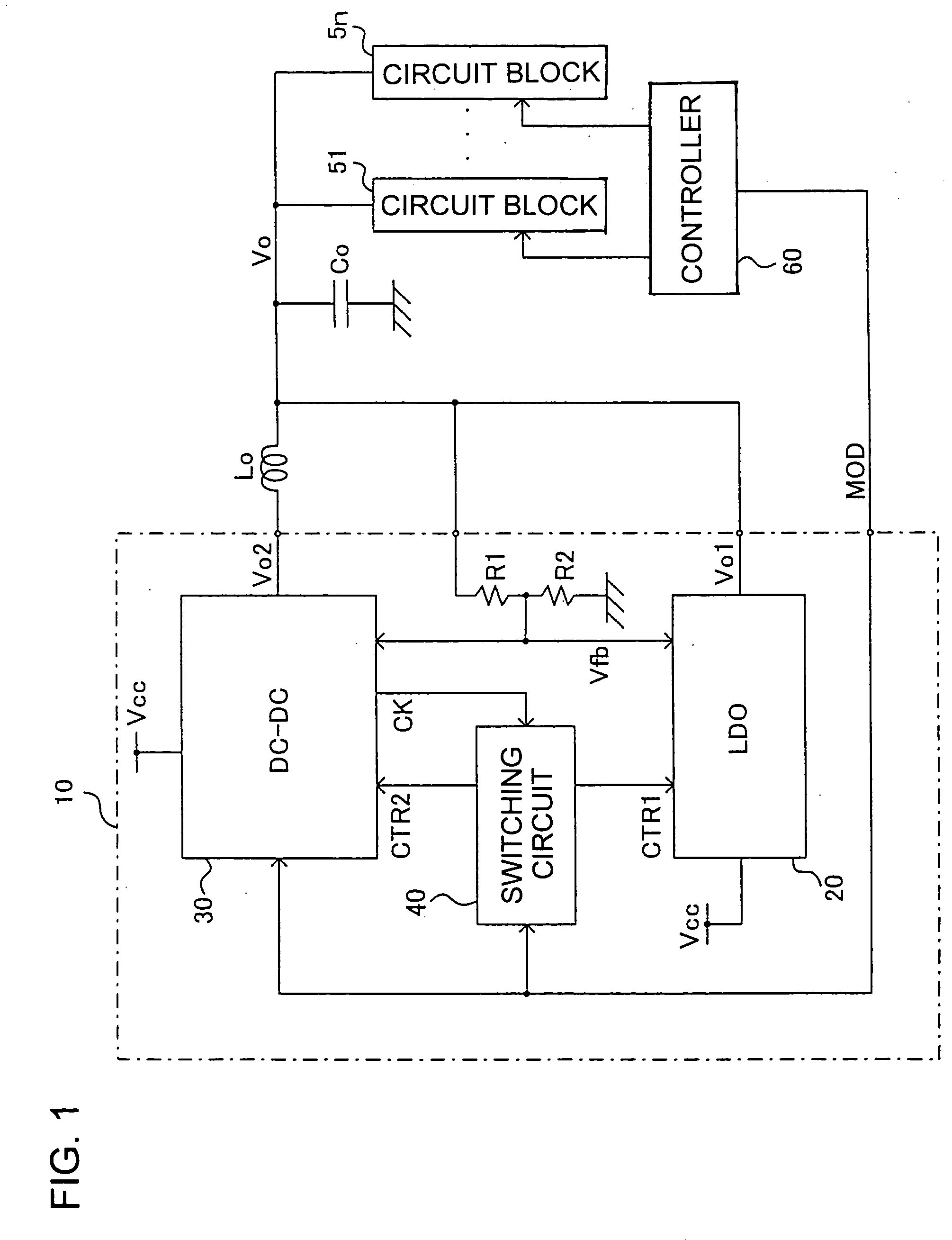
[0095]FIG. 1 is a diagram showing structures of a power supply unit and a portable apparatus in accordance with the invention. A power supplying IC 10 shown in FIG. 1 comprises: [0096] a series regulator or low-drop-out (LDO) regulator 20 in the form of a first power supply circuit for converting an input voltage Vcc supplied from a battery (not shown) into a predetermined output voltage Vo1 through continuous control of the input voltage Vcc; [0097] a switching DC-DC converter section 30 in the form of a second power supply circuit for generating a switching output voltage Vo2 through switching of the power source voltage Vcc; and [0098] a switching circuit 40 for switching the LDO and the switching DC-DC converter section 30.
[0099] In response to a mode instruction signal MOD received from an external controller 60 and in accordance with the level of the mode instruction signal MOD being high (H) or low (L), the switching circuit 40 switches a first enable signal CTR1 to be suppl...
second embodiment
[0156] As shown in FIG. 10, resistors R5-R8 are connected in series between the output end of the inverter INV1 and the drain of the PMOS transistor of the inverter INV1. A switch SW3 is connected in parallel with the resistor R5, a switch SW4 in parallel with the resistors R5 and R6, and a switch SW5 in parallel with resistors R5-R7. The switch SW3 is controlled by the first delay signal Sd1, the switch SW4 by the second delay signal Sd2, and the switch SW5 by the first enable signal CTR1. Thus, in the second embodiment shown herein, the DC-DC converter section 30 is supplied with the first enable signal CTR1 in addition to the second enable signal.
[0157] In the delay time control means of FIG. 10, the time constant determined by the resistors R5-R8 and the capacitor Cd is gradually shortened in several steps by turning on the switches SW3-SW5 in sequence when the DC-DC converter section 30 is enabled, thereby changing the dead time in multiple steps from a predetermined long time ...
third embodiment
[0177]FIGS. 14-16 shows a power supply unit in accordance with the invention and its gain and phase characteristics as functions of frequency.
[0178]FIG. 14 shows in detail the structure of an error amplification circuit 33 of the third embodiment, explicitly showing its error amplifier 33a and feedback loops. The error amplification circuit 33 corresponds to the error amplification circuit 33 of FIG. 3. In this configuration, the feedback voltage Vfb is input to the inverting input end of the error amplification circuit 33 via serially connected resistors R9 and R10. In addition, a resistor R11 and the feedback capacitor Cf are connected in series between the output end of the error amplification circuit 33 and the inverting input end thereof. A switch SW7 and a resistor R12 connected in series are connected in parallel with the feedback capacitor Cf. A switch SW6 is connected in parallel with a resistor R10.
[0179] These switches SW6 and SW7 are controlled by the first enable signa...
PUM
 Abstract
Description
Claims
Application Information
 - R&D
- Intellectual Property
- Life Sciences
- Materials
- Tech Scout
- Unparalleled Data Quality
- Higher Quality Content
- 60% Fewer Hallucinations
Browse by: Latest US Patents, China's latest patents, Technical Efficacy Thesaurus, Application Domain, Technology Topic, Popular Technical Reports.
© 2025 PatSnap. All rights reserved.Legal|Privacy policy|Modern Slavery Act Transparency Statement|Sitemap|About US| Contact US: help@patsnap.com


