System, method, and apparatus for multilevel UV molding lithography for air bearing surface patterning

a technology of air bearings and lithography, applied in the field of air bearing surface improvement, can solve the problems of affecting the patterning function, the thickness of the pancakes is too large to allow its removal, and the patterning function is at risk, so as to improve the de-molding properties, improve the accuracy, and improve the effect of accuracy

Inactive Publication Date: 2005-09-01
WESTERN DIGITAL TECH INC
View PDF15 Cites 20 Cited by
  • Summary
  • Abstract
  • Description
  • Claims
  • Application Information

AI Technical Summary

Benefits of technology

[0010] UV molding from elastomeric masters on thin bendable backplanes allows replication of UV-cured resist patterns with high accuracy. The strength of this method compared to imprint lithography is its ability to accommodate large substrate topographies and its improved de-molding properties. Successful implementation of this concept requires the formation of a transparent UV-stable conformal stamp. The backplane of the stamps is laminated from a thin glass (approximately 70 microns) and a thin polymer layer (approximately 80 microns) to cope with the slider array co-planarity variation while being sturdy enough to withstand a manufacturing environment. With this configuration, co-planarity variations in step height across a gap of about 300 microns between sliders can be as large as 20 microns, otherwise the sliders can be tilted with respect to the plane of the carrier. To cope with co-planarity variations of about 8 microns, the backplanes of the stamps are formed from a laminate of 30-micron glass and 40-micron polymer, which may be insufficiently stable in a manufacturing environment.
[0011] One of the disadvantages of molding from elastomeric masters is their susceptibility to deformation. As the stamp is pushed onto a slider substrate that is coated with viscous prepolymer, a dome-like deformation is induced in the stamp, which remains as a “pancake” of polymer after the cure. The thickness of the pancakes is dependent on the size of the contact zone. To overcome this difficulty, an initial ash process is used to remove a layer of resist that is thicker than the maximum pancake thickness while not etching the ceramic substrate. For very large zones of polymer displacement, the thickness of the pancakes can become too large to allow their removal while maintaining sufficient resist thickness contrast for subsequent processes. In such a case, grooves can be added to the patterning stamp to facilitate the removal of pre-polymer from these zones. Adding grooves may seem to be detrimental to the patterning function, but calculations show that a balanced network of capillaries can efficiently reduce the maximum thickness of polymer in these zones.
[0012] To improve slider array flatness, a bonding pad is provided having flat, elastomeric sticky protrusions separated by grooves or a drainage channel that allows the air or another medium to escape when a flat object is placed on it at high speed. “High speed” means that a pressure of greater than 1 bar can build up in the medium at a gap height of about 0.2 microns or more. The sticky elastomeric protrusions are part of an elastomeric layer that is held on a backplane. The elastomeric layer can be siloxane rubber such as poly(dimethylsiloxane). The material is rubber elastic and relaxes to the original shape after release of mechanical stress.

Problems solved by technology

One of the disadvantages of molding from elastomeric masters is their susceptibility to deformation.
For very large zones of polymer displacement, the thickness of the pancakes can become too large to allow their removal while maintaining sufficient resist thickness contrast for subsequent processes.
Adding grooves may seem to be detrimental to the patterning function, but calculations show that a balanced network of capillaries can efficiently reduce the maximum thickness of polymer in these zones.

Method used


Image

  • System, method, and apparatus for multilevel UV molding lithography for air bearing surface patterning
  • System, method, and apparatus for multilevel UV molding lithography for air bearing surface patterning
  • System, method, and apparatus for multilevel UV molding lithography for air bearing surface patterning

Examples


Embodiment Construction

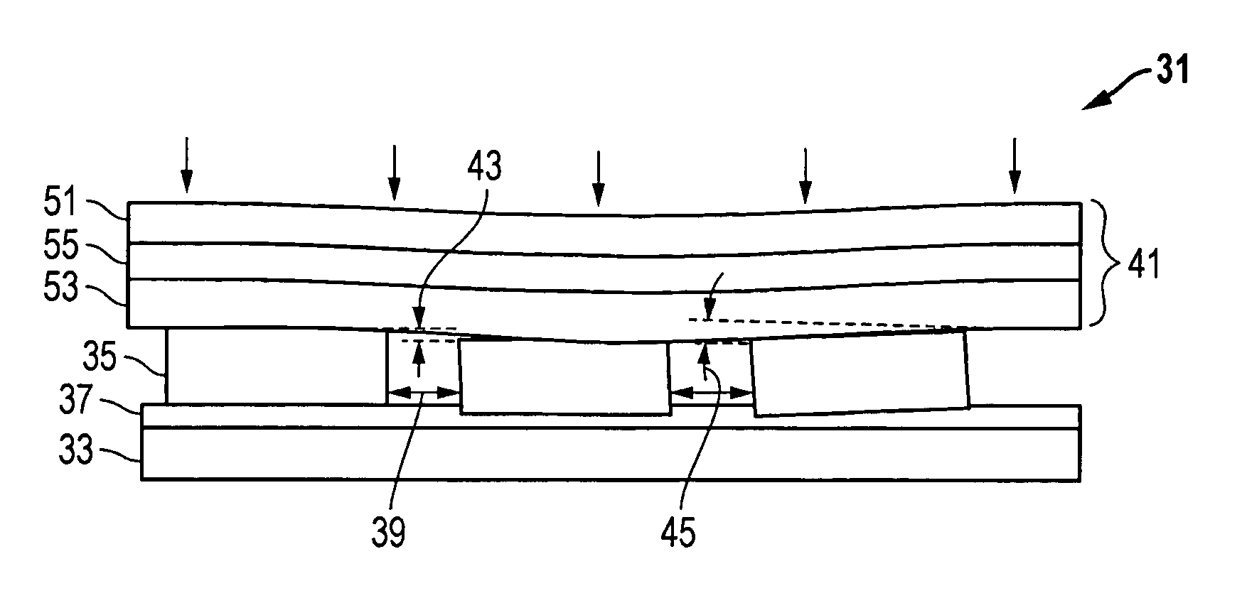
[0044] Referring to FIG. 1, one embodiment of a system 31 for replicating resist patterns with high accuracy is shown (not drawn to scale). System 31 is well suited for the processing and UV molding of workpieces, such as sliders in individual slider array processing systems. The system 31 comprises a carrier 33 having a plurality of workpieces 35 mounted thereto with a bonding material 37. Ideally, adjacent ones of the workpieces 35 are spaced apart from each other by a gap 39 of approximately 30 to 300 microns.

[0045] The system 31 also utilizes a stamp 41 for accommodating co-planarity variations between the workpieces 35. Variations between the workpieces 35 may include a step height 43 and a tilt angle 45. The step height 43 is defined as the vertical distance between the uppermost surfaces of the workpieces 35. In one version, the maximum value of the step height 43 that can be accommodated by the stamp 41 is approximately 1.2 microns. The tilt angle 45 is defined as the angle...


PUM

PropertyMeasurementUnit
thicknessaaaaaaaaaa
thicknessaaaaaaaaaa
step heightaaaaaaaaaa

Abstract

UV molding from elastomeric masters on thin bendable backplanes that allow replication of UV-cured resist patterns with high accuracy is disclosed. This design accommodates large substrate topographies, has improved de-molding properties, and facilitates two-in-one lithography and assembly of the sliders on topographically structured elastomeric sticky pads. The combination of sticky pad assembly and two-in-one lithography allows an all-in-one harmony process based on UV-molding. These features cure prior art technical problems of the harmony process while significantly reducing cost.

Description

BACKGROUND OF THE INVENTION [0001] 1. Technical Field [0002] The present invention relates in general to improved processing of air bearing surfaces and, in particular, to an improved system, method, and apparatus for multilevel UV molding lithography for air bearing surface patterning. [0003] 2. Description of the Related Art [0004] Thin film inductive heads and magneto-resistive read heads require for their operation a very small constant effective magnetic spacing between their pole tips and the magnetic medium. This spacing has to be kept constant while the head travels with respect to the rotating disk at a relative speed of several meters per second. Air bearings have been found to be most efficient to guarantee this constant spacing even at variable operation modes caused by the head descending from the headrest or during large external acceleration. An air bearing is a carefully designed airfoil on the disk-facing side of the physical structure carrying both the read and wri...

Claims


Application Information

Patent Timeline
Patent Type & Authority Applications(United States)
IPC IPC(8): B05D5/00G03F7/00
CPCB82Y10/00G03F7/0017G03F7/0002B82Y40/00
Inventor BIETSCH, ALEXANDERCHAW, MICHAEL W.LAHIRI, ASHOKMCFADYEN, IAN ROBSONMICHEL, BRUNOTHURBER, MARK C.
Owner WESTERN DIGITAL TECH INC
Why Eureka
Try Eureka