Bone shaping device for knee replacement

a knee replacement and bone shaping technology, applied in the field of joint replacement surgery devices, can solve the problems of inability to accurately register the successive cuts, requiring a considerable amount of surgical time and effort, and reducing the time so as to improve the accuracy and overall consistency, and reduce the time taken to cut and shape the bone surfaces. , the effect of reducing the time taken

Inactive Publication Date: 2005-09-01
WALKER PETER STANLEY +1
View PDF8 Cites 25 Cited by
  • Summary
  • Abstract
  • Description
  • Claims
  • Application Information

AI Technical Summary

Benefits of technology

[0010] The cutting blades are saw-like in shape and function and are intended to engage the bone to be shaped and cut prior to the engagement of the shaping surfaces. The shaping surfaces are meant to engage the bone to be shaped subsequent to the cutting blades and resemble a rasp-like surface which, through the vibratory movements of the device, grind down the bone to its final and intended configuration. The extent of the vibration is sufficient to reciprocate the cutting blades in a side-to-side manner and, at a short time later, to provide the necessary reciprocating motion to the rasp-like shaping surfaces for shaping and configuring the other portions of the bone.
[0011] Using the above described methodology, there is a significant reduction in the time taken to cut and shape the bone surfaces. There is also realized an increase i...

Problems solved by technology

Due to the successive cuts that are made separately, there is the possibility of a resulting lack of accurate registration between the successive cuts.
However, this mis-registration becomes more important when a boney ingrowth surface is used on the components.
Under these circumstances, a more precise fit is required between the bone and artificial component which requires a considerable amount of surg...

Method used


Image

  • Bone shaping device for knee replacement
  • Bone shaping device for knee replacement
  • Bone shaping device for knee replacement

Examples


Embodiment Construction

[0030] Reference will now be made in detail to the preferred embodiment of the present invention, an example of which is illustrated in the accompanying drawings.

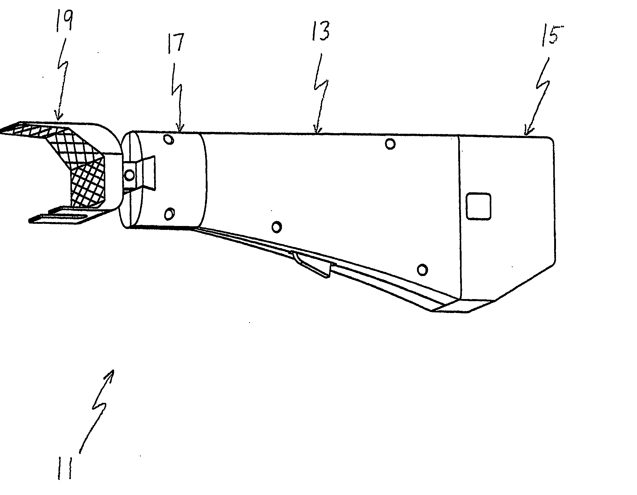
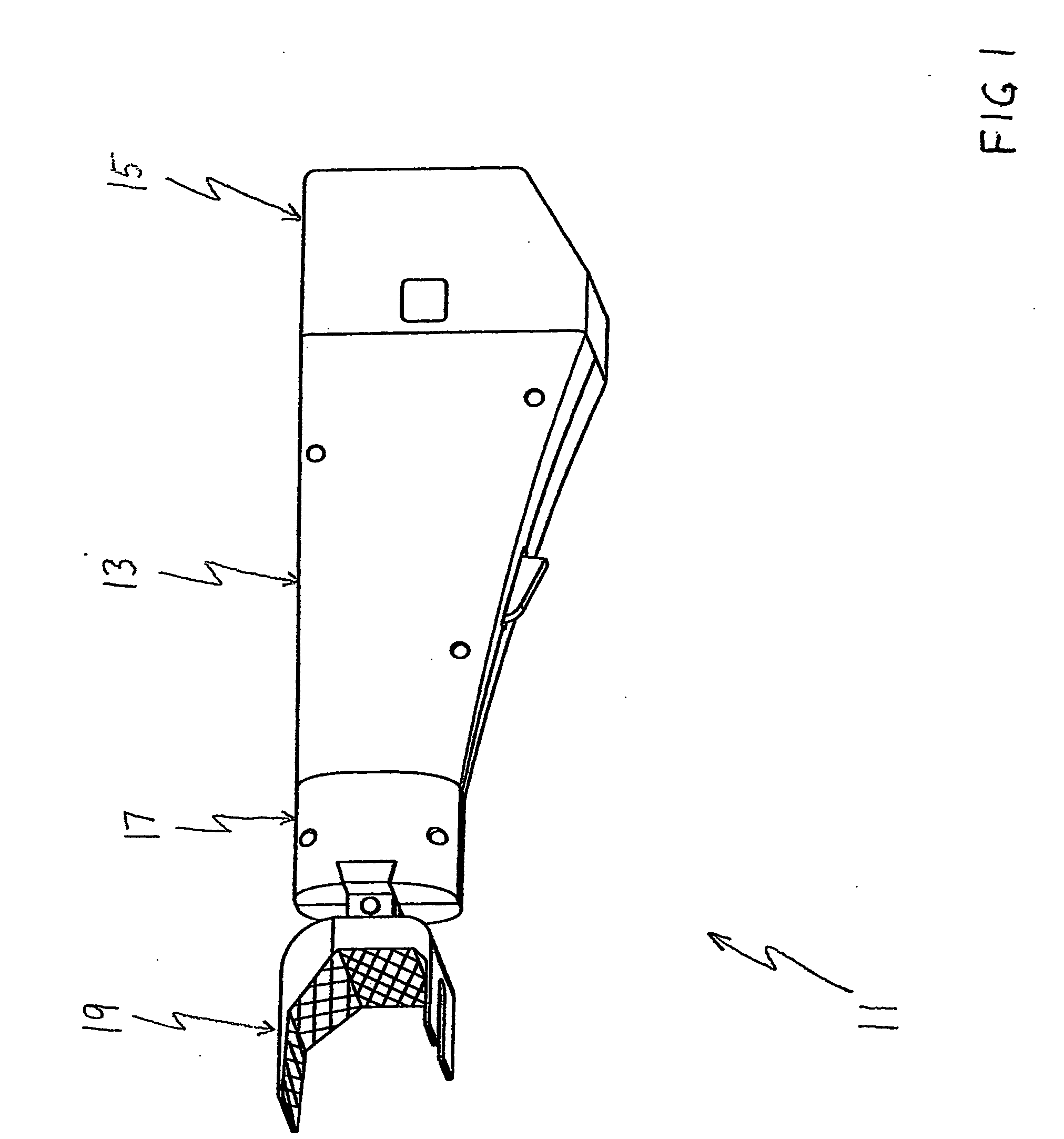
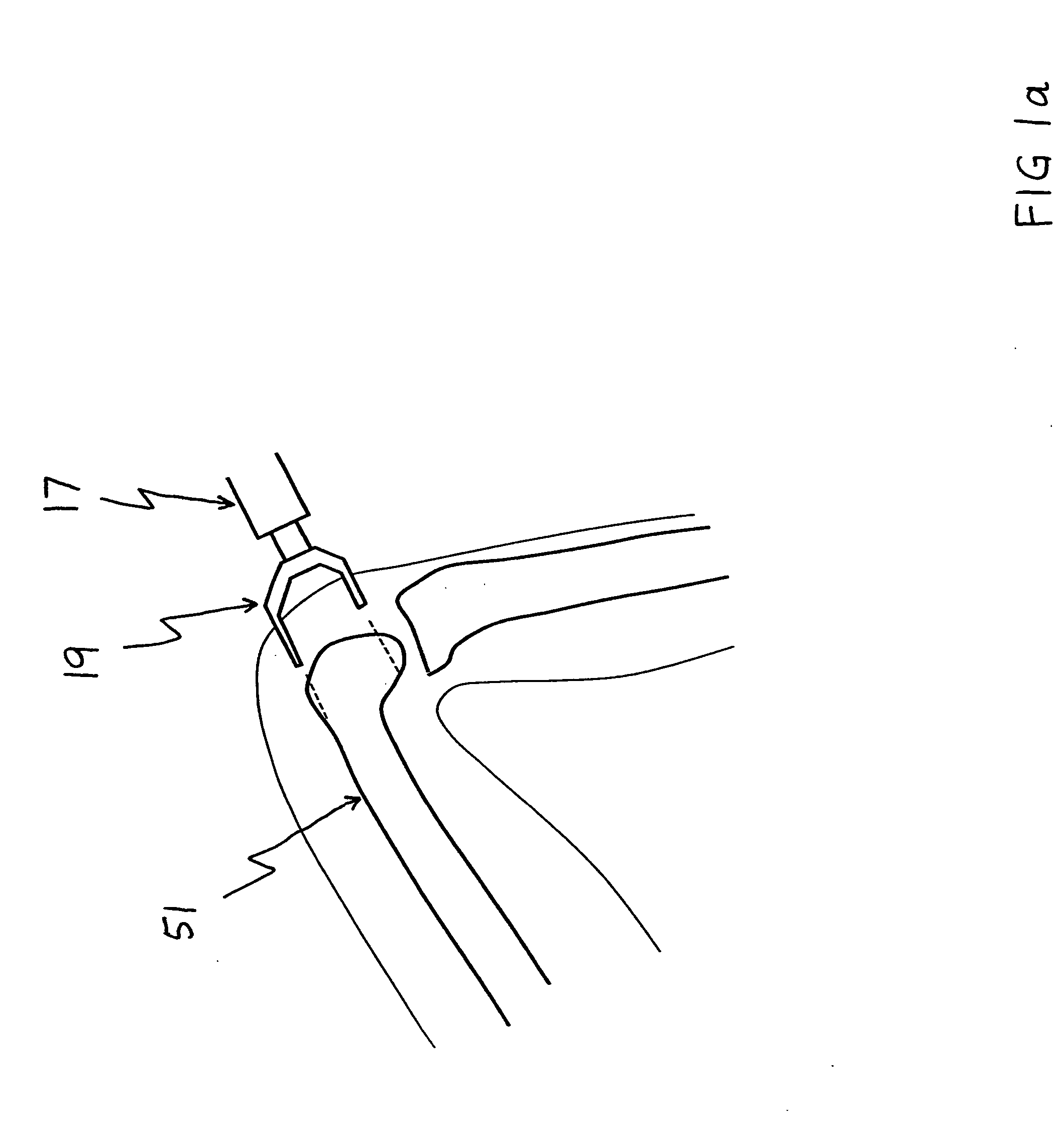
[0031] The preferred embodiment of the present invention is illustrated at 11 in FIG. 1. The device is adapted for cutting and shaping during use on the distal femur. The surgery is normally performed with the patient lying down and with the knee flexed at an angle of about 110 degrees as shown in FIG. 1a.

[0032] The device shown consists of a self-powered unit which is an advantage for use in the operating room. The main part of the outer casing 13 contains the motor 25 and hand switch 23 as shown in FIG. 2. The outer casing 13 also functions as a handle for the device. The end of the casing 15 contains the battery pack. The front of the casing 17 contains the mechanism for converting the rotary motion of the motor to side-to-side reciprocating motion. The shaping head 19 is attached to the end of the mechanism and hence ...


PUM


Abstract

A bone surgery device with a reciprocating cutting head. The device comprises several sets of shaping surfaces sometimes including cutting blades, which are located and oriented so as to shape the distal end of the femur and the proximal end of the tibia for total knee replacements and unicompartmental knee replacements. The device, which may be hand directed or aided by spatial and directional guiding mechanisms or an optical navigation system, may also include both coolant supply for controlling heat during bone cutting and shaping, and a suction method for carrying away fluid and debris. The device is substantially configured to the artificial joint component to be attached thereto.

Description

BACKGROUND OF THE INVENTION [0001] 1. The Field of the Invention [0002] The present invention relates to a device for use in joint replacement surgery such as total knee replacement where the entire bearing surfaces of the distal femur and proximal tibia are replaced. The invention is also related to unicompartmental knee replacements where only the lateral or medial compartments are replaced. The purpose of the invention is to cut and shape the distal end of the femur and the proximal end of the tibia so that the artificial components to be installed will precisely and accurately fit on their respective bones. Use of the device during knee replacement surgery increases the accuracy with which the artificial components fit to the bones and achieves a more consistent overall alignment of the femur and the tibia. Use of the device reduces the time to cut and shape the bone surfaces and is consistent with so-called minimally-invasive surgery. [0003] 2. Background of the Invention [0004...

Claims


Application Information

Patent Timeline
IPC IPC(8): A61B17/14A61B17/16A61B19/00A61M1/00
CPCA61B17/14A61B17/1659A61B17/1668A61B17/1675A61B19/5244A61B17/148A61B2017/320028A61B2019/5255A61B2019/5272A61B2217/005A61B2217/007A61B2017/1651A61B34/20A61B2034/2055A61B2034/2072A61B17/142
Inventor WALKER, PETER STANLEYWEI, CHIH-SHING
Owner WALKER PETER STANLEY
Why Eureka
Try Eureka