Expandable stents and method for making same

a technology of endoprosthesis and expandable stents, which is applied in the field of expandable endoprosthesis devices to achieve the effects of maintaining compliance, facilitating insertion, and facilitating insertion

Inactive Publication Date: 2005-09-01
ABBOTT CARDIOVASCULAR
View PDF99 Cites 5 Cited by
  • Summary
  • Abstract
  • Description
  • Claims
  • Application Information

AI Technical Summary

Benefits of technology

[0008] The stent of the invention generally includes a plurality of radially expandable cylindrical elements which are relatively independent in their ability to expand and to flex relative to one another. The individual radially expandable cylindrical elements of the stent are dimensioned so as to be longitudinally shorter than their own diameters. Interconnecting elements or struts extending between adjacent cylindrical elements provide increased stability and a preferable position to prevent warping of the stent upon the expansion thereof. The resulting stent structure is a series of radially expandable cylindrical elements which are spaced longitudinally close enough so that small dissections in the wall of a body lumen may be pressed back into position against the lumenal wall, but not so close as to compromise the longitudinal flexibilities of the stent. The individual cylindrical elements may rotate slightly relative to adjacent cylindrical elements without significant deformation, cumulatively giving a stent which is flexible along its length and about its longitudinal axis but is still very stiff in the radial direction in order to resist collapse.
[0010] The presently preferred structure for the expandable cylindrical elements which form the stents of the present invention generally circumferential undulating pattern, e.g. serpentine. The transverse cross-section of the undulating component of the cylindrical element is relatively small and preferably has an apect ratio of about two to one to about 0.5 to one. A one to one apect ratio has been found particularly suitable. The open reticulated structure of the stent allows for the perfusion of blood over a large portion of the arterial wall which can improve the healing and repair of a damaged arterial lining.
[0011] The radial expansion of the expandable cylinder deforms the undulating pattern thereof similar to changes in a waveform which result from decreasing the waveform's amplitude and the frequency. Preferably, the undulating patterns of the individual cylindrical structures are in phase with each other in order to prevent the contraction of the stent along its length when it is expanded. The cylindrical structures of the stent are plastically deformed when expanded (except with NiTi alloys) so that the stent will remain in the expanded condition and therefore they must be sufficiently rigid when expanded to prevent the collapse thereof in use. During expansion of the stent, portions of the undulating pattern will tip outwardly resulting in projecting members on the outer surface of the expanded stent. These projecting members tip radially outwardly from the outer surface of the stent and embed in the vessel wall and help secure the expanded stent so that it does not move once it is implanted.
[0013] The elongated elements which interconnect adjacent cylindrical elements should have a transverse cross-section similar to the transverse dimensions of the undulating components of the expandable cylindrical elements. The interconnecting elements may be formed in a unitary structure with the expandable cylindrical elements from the same intermediate product, such as a tubular element, or they may be formed independently and connected by suitable means, such as by welding or by mechanically securing the ends of the interconnecting elements to the ends of the expandable cylindrical elements. Preferably, all of the interconnecting elements of a stent are joined at either the peaks or the valleys of the undulating structure of the cylindrical elements which for the stent. In this manner there is no shortening of the stent upon expansion.
[0014] The number and location of elements interconnecting adjacent cylindrical elements can be varied in order to develop the desired longitudinal flexibility in the stent structure both in the unexpanded as well as the expanded condition. These properties are important to minimize alteration of the natural physiology of the body lumen into which the stent is implanted and to maintain the compliance of the body lumen which is internally supported by the stent. Generally, the greater the longitudinal flexibility of the stent, the easier and the more safely it can be delivered to the implantation site.
[0015] In a presently preferred embodiment of the invention the stent is conveniently and easily formed by coating stainless steel tubing with a material resistant to chemical etching, removing portions of the coating to expose portions of underlying tubing which are to be removed to develop the desired stent structure. The exposed portions of the tubing are removed by chemically etching from the tubing exterior leaving the coated portion of the tubing material in the desired pattern of the stent structure. The etching process develops smooth openings in the tubing wall without burrs or other artifacts which are characteristic of mechanical or laser machining processes in the small sized products contemplated. Moreover, a computer controlled laser patterning process to remove the chemical resistive coating makes photolithography technology adaptable to the manufacture of these small products. The forming of a mask in the extremely small sizes needed to make the small stents of the invention would be a most difficult task. A plurality of stents can be formed from one length of tubing by repeating the stent pattern and providing small webs or tabs to interconnect the stents. After the etching process, the stents can be separated by severing the small webs or tabs which connect them.

Problems solved by technology

One of the difficulties encountered using prior stents involved maintaining the radial rigidity needed to hold open a body lumen while at the same time maintaining the longitudinal flexibility of the stent to facilitate its delivery.

Method used


Image

  • Expandable stents and method for making same
  • Expandable stents and method for making same
  • Expandable stents and method for making same

Examples


Embodiment Construction

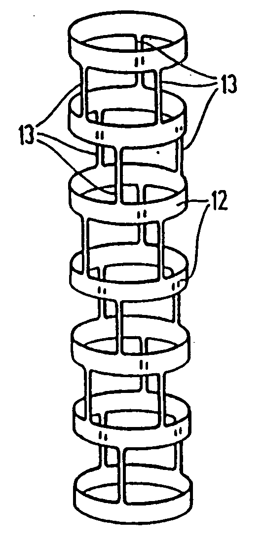
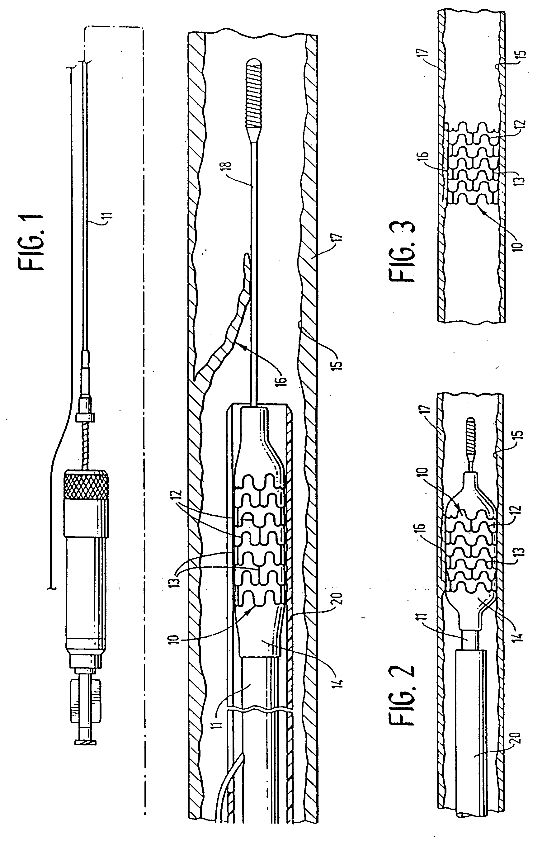
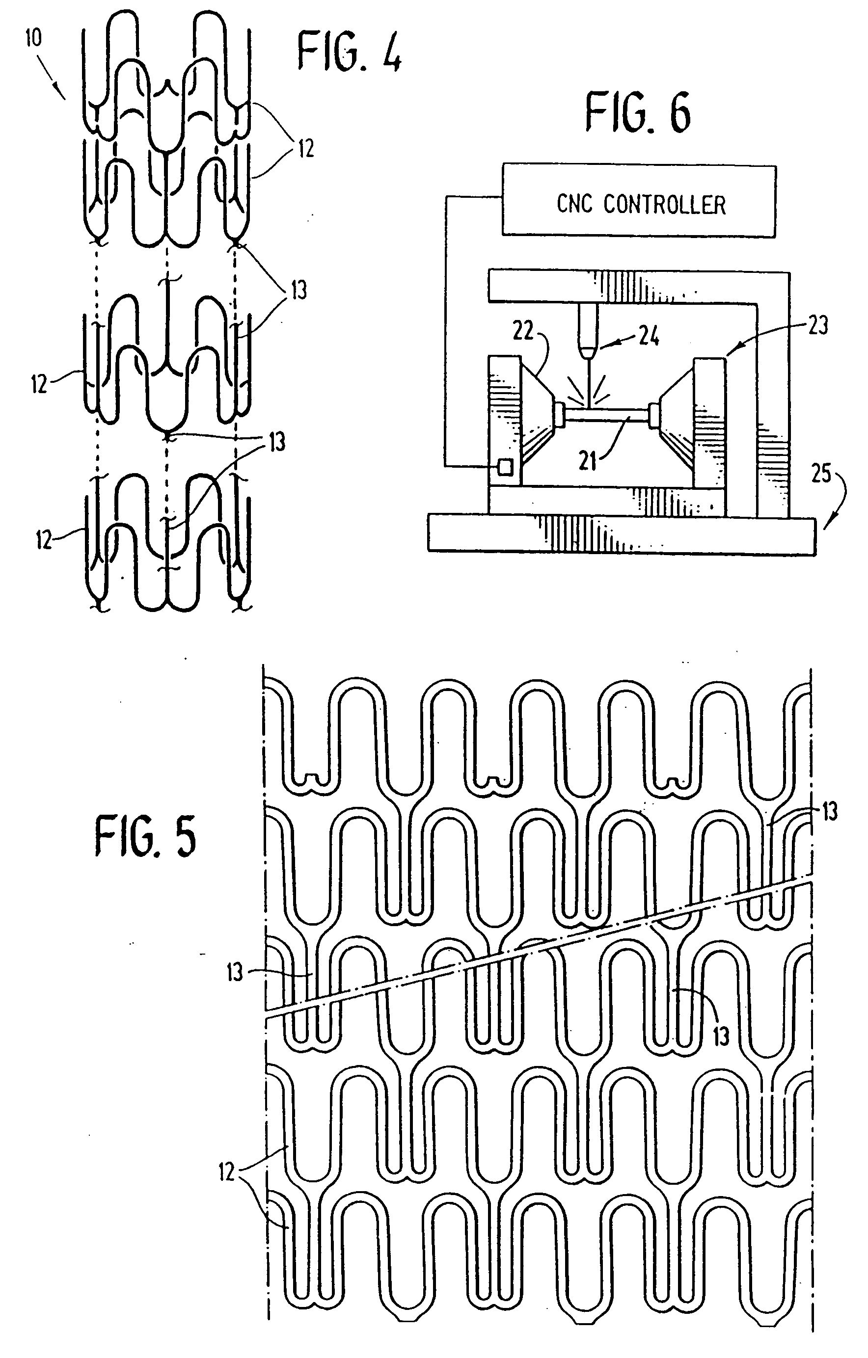
[0028]FIG. 1 illustrates a stent 10 incorporating features of the invention which is mounted onto a delivery catheter 11. The stent generally comprises a plurality of radially expandable cylindrical elements 12 disposed generally coaxially and interconnected by elements 13 disposed between adjacent cylindrical elements. The delivery catheter 11 has an expandable portion or balloon 14 for expanding of the stent 10 within an artery 15. The artery 15, as shown in FIG. 1 has a dissected lining 16 which has occluded a portion of the arterial passageway.

[0029] The delivery catheter 11 onto which the stent 10 is mounted, is essentially the same as a conventional balloon dilatation catheter for angioplasty procedures. The balloon 14 may be formed of suitable materials such as polyethylene, polyethylene terephthalate, polyvinyl chloride, nylon and ionomers such as Surlyn® manufactured by the Polymer Products Division of the Du Pont Company. Other polymers may also be used. In order for the ...


PUM

PropertyMeasurementUnit
outer diameteraaaaaaaaaa
thicknessaaaaaaaaaa

Abstract

The invention is directed to an expandable stent for implantation in a body lumen, such as an artery, and a method for making it from a single length of tubing. The stent consists of a plurality of radially expandable cylindrical elements generally aligned on a common axis and interconnected by one or more interconnective elements. The individual radially expandable cylindrical elements consist of ribbon-like material disposed in an undulating pattern. Portions of the expanded stent project outwardly into engagement with the vessel wall to more securely attach the stent.

Description

RELATED APPLICATIONS [0001] This application is a continuation-in-part of co-pending U.S. patent application Ser. No. 08 / 164,986 filed Dec. 9, 1993, which is a continuation application of U.S. Ser. No. 07 / 783,558 filed Oct. 28, 1991, now abandoned.BACKGROUND OF THE INVENTION [0002] This invention relates to expandable endoprosthesis devices, generally called stents, which are adapted to be implanted into a patient's body lumen, such as blood vessel, to maintain the patency thereof. These devices are very useful in the treatment of atherosclerotic stenosis in blood vessels. [0003] Stents are generally tubular-shaped devices which function to hold open a segment of a blood vessel or other anatomical lumen. They are particularly suitable for use to support and hold back a dissected arterial lining which can occlude the fluid passageway therethrough. [0004] Further details of prior art stents can be found in U.S. Pat. No. 3,868,956 (Alfidi et al.); U.S. Pat. No. 4,512,338 (Balko et al.)...

Claims


Application Information

Patent Timeline
Patent Type & Authority Applications(United States)
IPC IPC(8): A61F2/00A61F2/86A61F2/88C23F1/02C23F1/04
CPCA61F2/848Y10T29/49995A61F2/88A61F2/91A61F2/915A61F2/958A61F2002/91533A61F2002/9155A61F2002/91558A61F2002/91575A61F2210/0019A61M2025/1081C23F1/02C23F1/04A61F2/89Y10S623/901Y10S623/921Y10S623/903A61F2/86
Inventor LAU, LILIPHARTIGAN, WILLIAM M.FRANTZEN, JOHN J.
Owner ABBOTT CARDIOVASCULAR
Why Eureka
Try Eureka