Lens system

a technology of lens and camera body, applied in the field of lens system, can solve the problems of so-called slippage phenomenon, high time and labor requirements, etc., and achieve the effect of high-accuracy photographing data

Inactive Publication Date: 2005-09-08
FUJI PHOTO OPTICAL CO LTD
View PDF2 Cites 5 Cited by
  • Summary
  • Abstract
  • Description
  • Claims
  • Application Information

AI Technical Summary

Benefits of technology

[0018] The lens system of the present invention may have a taking lens having an adjustment unit for adjusting a flange back, and a compensation unit for compensating a change in the photographing data stemming from the adjusting of the flange back. According to the present invention, even when an optical characteristic is changed by means of flange back adjustment, highly-accurate photographing data can be offered to an external system.
[0019] The output unit may output the photographing data to a virtual system. The lens system of the present invention is particularly effective when used in a virtual system requiring photographing data to be used for setting photographing conditions of a virtual camera, such as an angle of view, an object distance, and a principal point position, all pertaining to an actual camera.
[0020] According to the lens system of the present invention, when the lens system is used in a video processing system, such as a virtual system, the video processing system does not need to compute the required photographing data. Therefore, the time and labor required by settings, such as advance measurement and registration, by the user, of lens data required to compute the photographing data are curtailed. Moreover, high-precision photographing data can also be offered.

Problems solved by technology

Thus, the operations require much time and labor.
If the number of points is reduced for saving time, there will arise a so-called slippage phenomenon of a mismatch occurring between a live video and an electronic video.

Method used


Image

  • Lens system
  • Lens system
  • Lens system

Examples


Embodiment Construction

[0025] A preferred embodiment of a lens system according to the present invention will be described in detail hereinbelow by reference to the accompanying drawings.

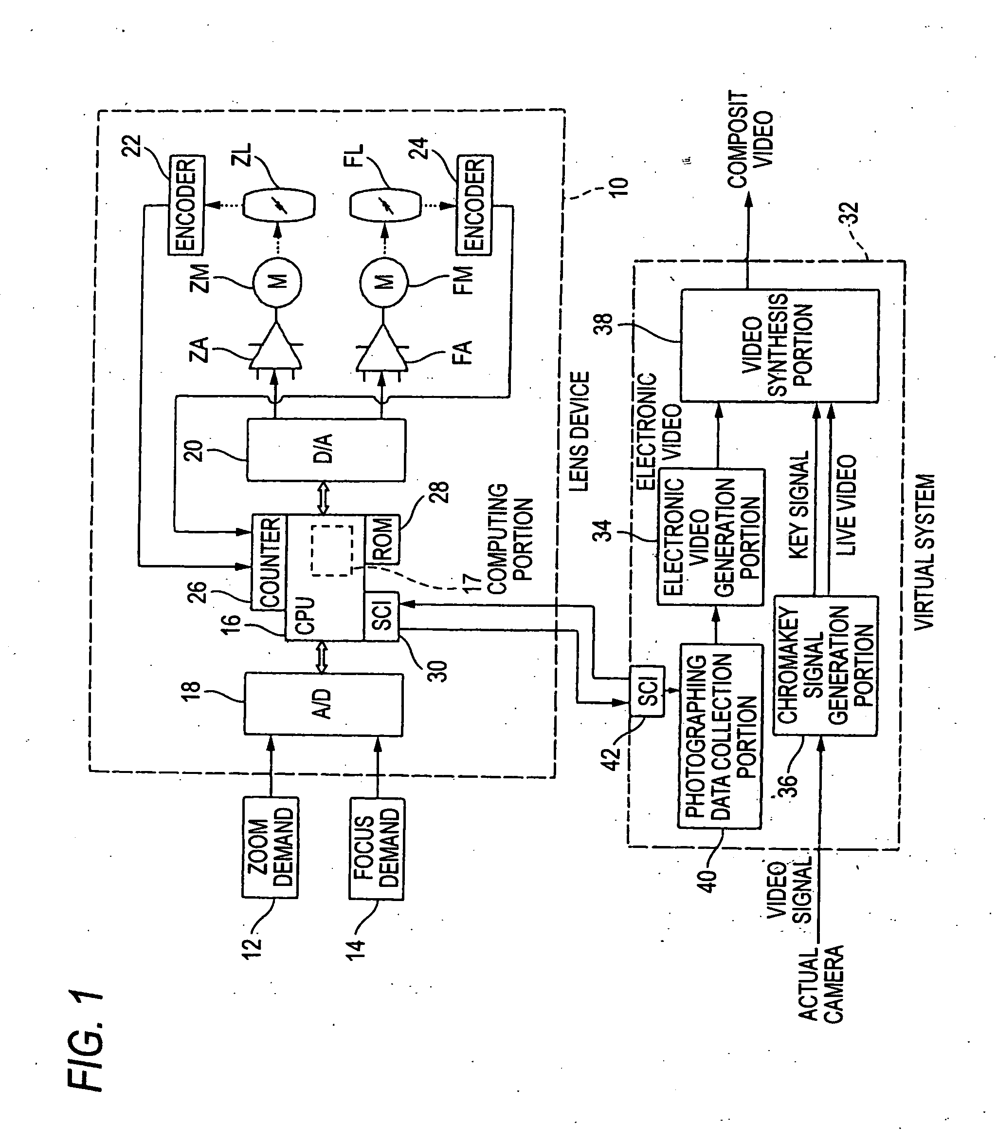
[0026]FIG. 1 is a block diagram showing the configuration of a lens system to which the present invention is applied, as well as the configuration of a virtual system.

[0027] The overview of a virtual system 32 will first be described. As illustrated in the drawing, the virtual system 32 is so-called a virtual studio. In this system, an actual video photographed with a blue background by means of a video camera for broadcasting or commercial purpose (i.e., an actual camera) is merged with an electronic video of a virtual space (i.e., a virtual studio) generated by a computer or the like, through use of a chromakey synthesis technique. This system photographs an actual image by means of the actual camera, and simultaneously generates a composite image.

[0028] As illustrated in the drawing, the virtual system 32 includes a...


PUM


Abstract

To provide a lens system which is to be used with a virtual system and which can curtail time and labor required by settings of the virtual system by outputting data pertaining to an angle of view, an object distance, and a principal point position, all being required by the virtual system, the lens device of an actual camera used for photographing an actual video to be used by the virtual system includes a CPU determining information about the angle of view, the object distance, and the principal point position, all being required to set a virtual camera in the virtual system, on the basis of a zoom position and a focus position detected by encoders, and transmits the information to the virtual system.

Description

FIELD OF THE INVENTION [0001] The present invention relates to a lens system, and more particularly, to a lens system applied to a video synthesis system (or video processing system), such as a virtual studio. BACKGROUND OF THE INVENTION [0002] A technique for combining a live video captured by a television camera with an electronic image, or the like, generated by a computer is heavily used in recent TV broadcasts. A commonly-known technique for synthesizing videos (images) is a chromakey synthesis technique. According to this technique, when an image which would be a foreground subject of a synthesized image, such as a person, is acquired as a live video, the foreground subject is located in front of, e.g., a blue canvas (blue background), and captured by a television camera. As a result, a key signal to be used for distinguishing the area of the foreground subject from the area of the blue background is generated from the video signal. In accordance with the key signal, the image...

Claims


Application Information

Patent Timeline
Patent Type & Authority Applications(United States)
IPC IPC(8): G02B7/08G02B7/02G02B7/10H04N5/225H04N5/232H04N5/262
CPCG02B7/102H04N5/2224H04N23/60
Inventor SASAKI, TADASHI
Owner FUJI PHOTO OPTICAL CO LTD
Why Eureka
Try Eureka