
Method and circuit for adaptive equalization of multiple signals in response to a control signal generated from one of the equalized signals

a technology of adaptive equalization and control signal, applied in the direction of amplitude demodulation, line-fault/interference reduction, pulse technique, etc., can solve the problems of reducing the signal quality at the receiver end, increasing the chance of false detection of signals received, and almost unusable eye at the receiver, etc., to achieve simple and robust

Active Publication Date: 2005-09-08
LATTICE SEMICON CORP
View PDF16 Cites 59 Cited by
  • Summary
  • Abstract
  • Description
  • Claims
  • Application Information

AI Technical Summary

Benefits of technology

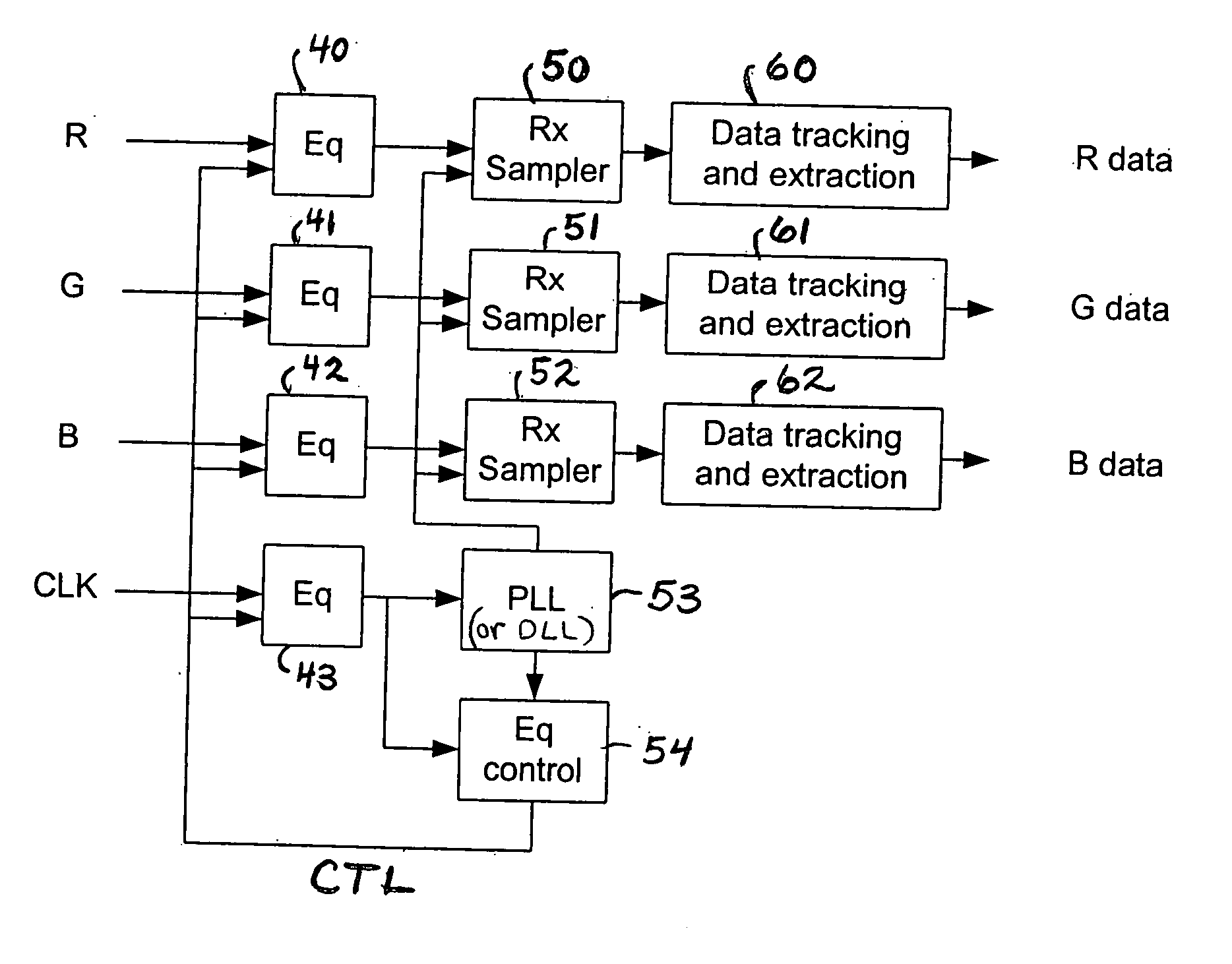
[0020] In a class of embodiments, the invention is an adaptive equalization circuit comprising at least two equalization filters (each coupled and configured to equalize a different signal in a manner at least partially determined by an equalization control signal) and control circuitry for generating the equalization control signal for use by all the equalization filters. Typically, each equalization filter is coupled to receive a signal that has propagated over a different channel of a multi-channel serial link. The control circuitry is coupled and configured to generate the equalization control signal in response to an equalized signal asserted at the output of one of the filters, and to assert the equalization control signal to all the filters. Typically, the equalization control signal is indicative of at least one equalization control value and is used to set at least one equalization parameter of each equalization filter (e.g., to control the amount of equalization applied by each filter). Adaptive equalization in accordance with preferred embodiments of the invention is much simpler and more robust than conventional adaptive equalization.
[0022] The control circuitry can be configured to assume that the input signal it receives is an equalized fixed pattern signal having a predetermined fixed pattern (e.g., an equalized clock signal having a periodic waveform that is known a priori). In this case, the control circuitry can easily be configured in accordance with the invention to generate the equalization control signal in response to the input signal it receives.
[0027] In some preferred embodiments, the stabilized signal is a stabilized version of an equalized clock signal and the control signal generation circuit acquires two samples of the equalized clock signal per clock cycle (i.e., per cycle of the equalized clock signal), at different times during the same half cycle of the equalized clock signal. The control signal generation circuit generates the equalization control signal by comparing the two samples or subtracting one sample from the other (and optionally filtering the result of such comparison or subtraction). The equalization control signal is indicative of the condition of equalization of the equalized clock signal, and is used to control each equalization filter of the adaptive equalization circuit. In implementations in which the equalization control signal is indicative of a value equal (or proportional) to the difference between each pair of samples generated in one clock cycle, the adaptive equalization circuit implements a control loop that operates to minimize the difference between the sample pairs and thereby achieve optimal equalization of the clock signal. When the adaptive equalization circuit is coupled to receive and equalize data signals and a clock signal that have been transmitted over different channels of a multi-channel serial link (the channels all having identical or similar transfer functions), use of the equalization control signal to equalize the data signals as well as the clock signal achieves optimal (or nearly optimal) equalization of each data signal as well as of the clock signal.

Problems solved by technology

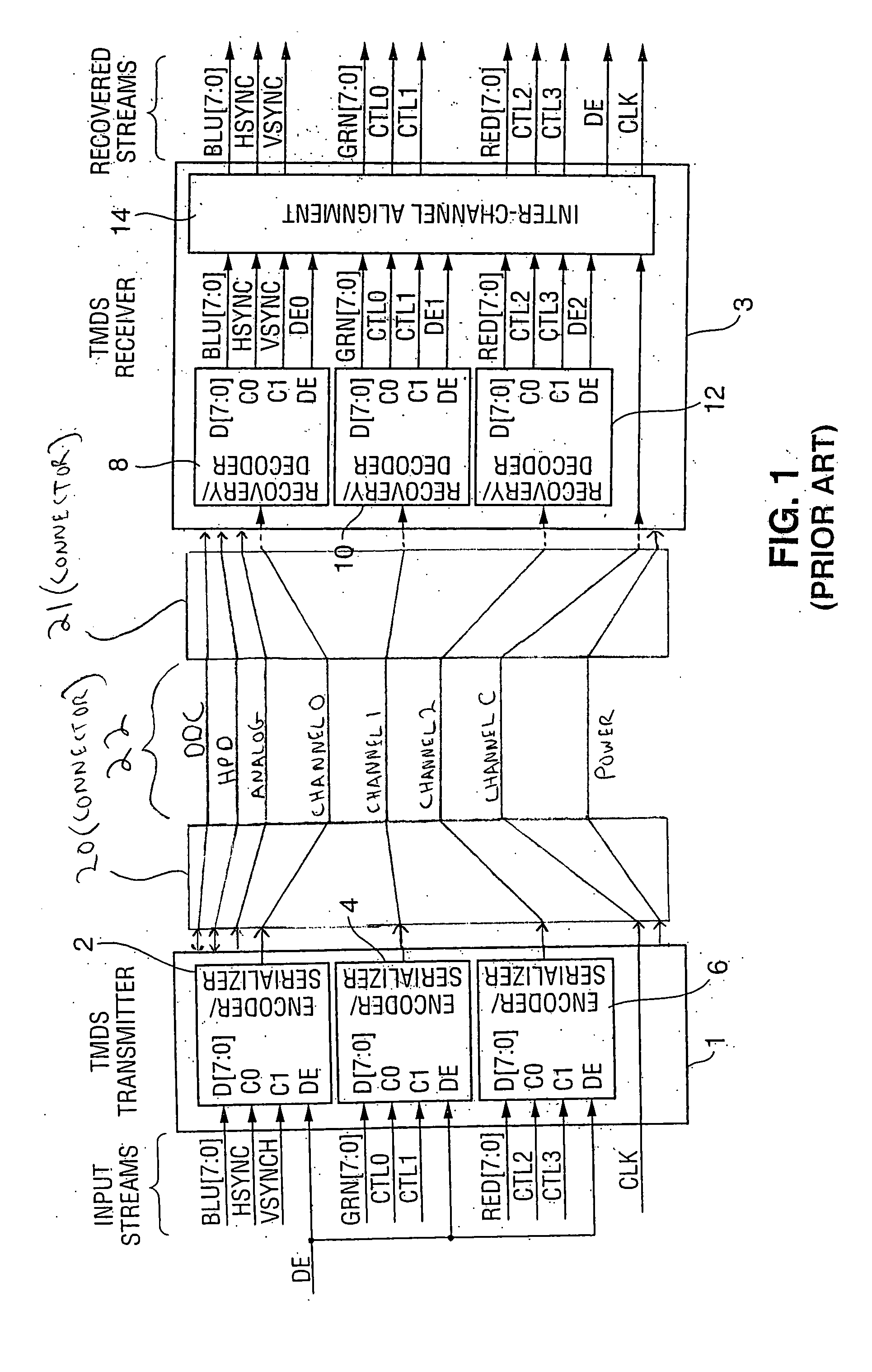
During high-speed serial data transmission over a link (a cable and / or connectors and / or PCB traces), the link itself introduces losses and dispersion which reduce the signal quality at the receiver end.
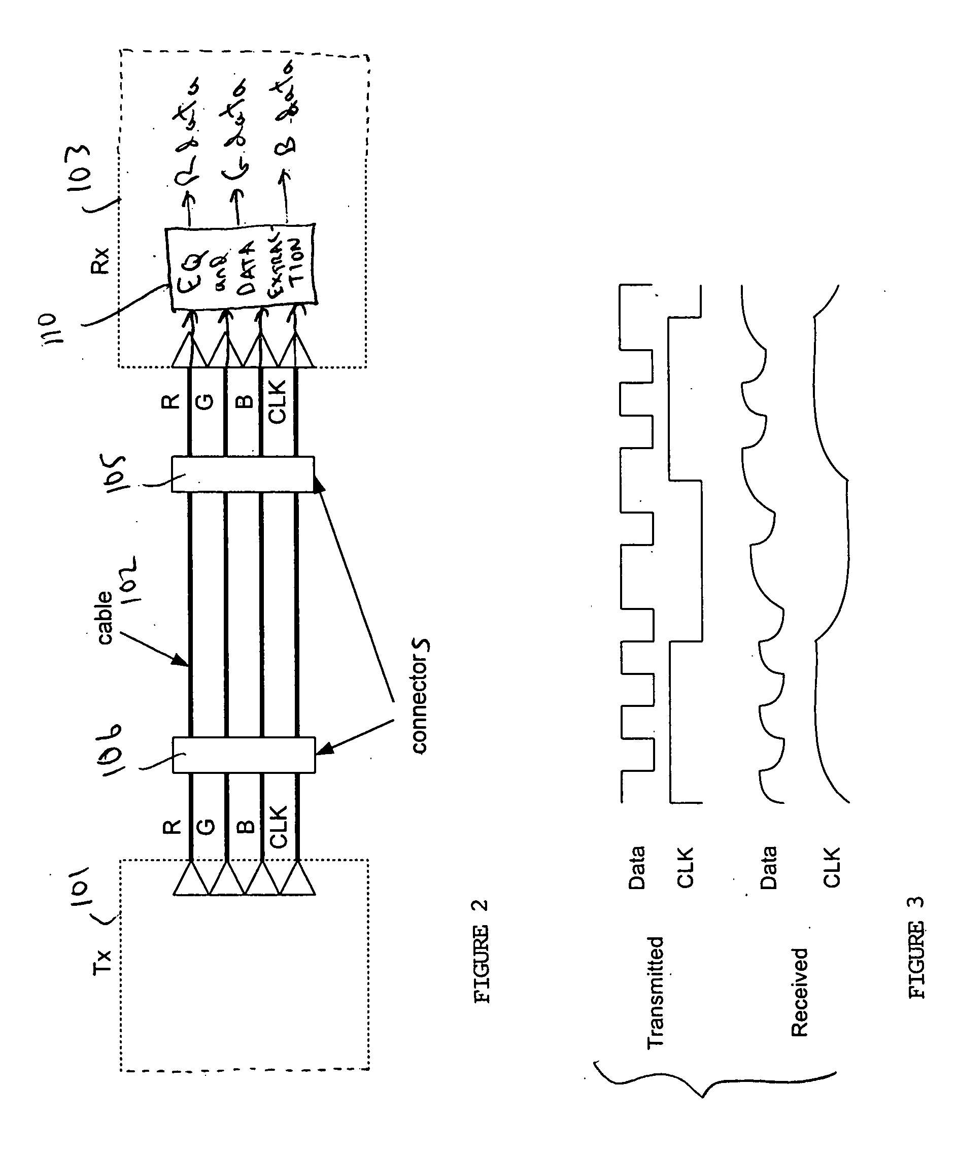
As the frequency of the transmitted signal and / or the transmission distance increases, the distortion due to frequency dependent delay and attenuation increases, increasing the chance of false detection of signals received and in some cases making the eye at the receiver almost unusable.
Transmission of signals indicative of data (e.g., video or audio data) to a receiver over a serial link degrades the data, for example by introducing time delay error (sometimes referred to as jitter) to the data.
The filter (to be referred to herein as a “cable filter,” although the link may consist of or include PCB traces) can cause inter-symbol interference (ISI).
However, circuitry for performing the attenuation estimation needed for adaptive equalization has been complex and difficult to implement.
However, equalization circuitry in a receiver cannot easily determine the optimum equalization filter to apply to a received signal unless the receiver knows what the transmitted signal looked like.

Method used


Image

  • Method and circuit for adaptive equalization of multiple signals in response to a control signal generated from one of the equalized signals
  • Method and circuit for adaptive equalization of multiple signals in response to a control signal generated from one of the equalized signals
  • Method and circuit for adaptive equalization of multiple signals in response to a control signal generated from one of the equalized signals

Examples


Embodiment Construction

[0044] In preferred embodiments, the invention is a method and apparatus for performing adaptive equalization on clock and data signals transmitted over different channels of a multi-channel serial link, where the link includes a clock channel (over which the clock signal propagates) and at least one data channel. A data signal is transmitted serially over each data channel. In alternative embodiments, the invention is a method and apparatus for performing adaptive equalization on a fixed pattern signal and at least one other signal transmitted over a multi-channel serial link. The following description of the preferred embodiments also applies to the alternative embodiments, with minor modifications that will be apparent to those of ordinary skill in the art (e.g., substitution of references to a transmitted fixed pattern signal for references to a transmitted clock signal).

[0045]FIG. 2 is a simplified block diagram of a system that embodies the invention. The FIG. 2 system includ...


PUM


Abstract

In preferred embodiments, an adaptive equalization circuit including at least two equalization filters (each for equalizing a signal transmitted over a multi-channel serial link) and control circuitry for generating an equalization control signal for use by all the filters. The control circuitry generates the control signal in response to an equalized signal produced by one of the filters, and asserts the control signal to all the filters. Preferably, one filter generates an equalized fixed pattern signal in response to a fixed pattern signal (e.g., a clock signal), each other filter equalizes a data signal, and the control circuitry generates the control signal in response to the equalized fixed pattern signal. In other embodiments, the invention is an adaptive equalization circuit including an equalization filter and circuitry for generating a control signal for the filter in response to a signal indicative of a predetermined fixed pattern, a receiver including an adaptive equalization circuit, a system including such a receiver, and a method for adaptive equalization of signals received over a multi-channel serial link.

Description

FIELD OF THE INVENTION [0001] The invention pertains to methods and circuits for adaptive equalization of signals transmitted over a multi-channel serial link (e.g., data and clock signals over different channels of a multi-channel serial link). BACKGROUND OF THE INVENTION [0002] The term “transmitter” is used herein in a broad sense to denote any device capable of transmitting data over a serial link, and optionally also capable of performing additional functions which can include encoding and / or encrypting the data to be transmitted. The term “receiver” is used herein in a broad sense to denote any device capable of receiving data that has been transmitted over a serial link, and optionally also capable of performing additional functions, which can include decoding and / or decryption of the received data, and other operations related to decoding, reception, or decryption of the received data. For example, the term receiver can denote a transceiver that performs the functions of a t...

Claims


Application Information

Patent Timeline
IPC IPC(8): H03D1/04H03K5/01
CPCH04L25/03019H03H7/30
Inventor KIM, OOKKIM, GYUDONG
Owner LATTICE SEMICON CORP
Learn More