Spectral gamma ray logging-while-drilling system

a gamma ray and logging technology, applied in the field of spectral gamma ray loggingwhiledrilling system, can solve the problems of low count rate and detector stabilization, low z materials that do not meet the structural requirements of lwd system, and gamma ray detectors undergo significant temperature changes, so as to minimize spectral degradation and maximize the measurement rate

Active Publication Date: 2005-09-15
WEATHERFORD CANADA
View PDF46 Cites 67 Cited by
  • Summary
  • Abstract
  • Description
  • Claims
  • Application Information

AI Technical Summary

Benefits of technology

[0013] The sensor element comprises one or more gamma ray detectors that are disposed as close as practical to the periphery of the tool. This minimizes intervening material between the one or more detectors and the source of gamma radiation, which is earth formation penetrated by the borehole. As a result of this detector geometry, spectral degradation is minimized and measured count rate is maximized for a given detector size. The detector geometry also allows an azimuthal spectral gamma ray measurement in a plane essentially perpendicular to the axis of the tool. The one or more gamma ray detectors preferably comprises a scintillation crystal optically coupled to a light sensitive device such as a photomultiplier tube. The detector element is calibrated under known conditions and at a “standard” detector gain. The sensor element can also contain a system, such as a magnetometer, that senses the orientation of the tool within the borehole.

Problems solved by technology

Low count rate and detector stabilization are major problems in any type of natural spectral LWD systems Most naturally occurring gamma radiation found in earth formations is emitted by potassium (K) and elements within the decay chains of uranium (U) and thorium (Th).
Low Z materials often do not meet structural requirements of LWD systems.
Gamma ray detectors undergo significant temperature changes during a logging operation.
Gain changes, often referred to as gain “shifts”, adversely affect gamma ray spectral analysis.
This compensation is especially difficult to achieve in LWD systems.
The data rates of available LWD telemetry systems between the downhole tool and surface equipment are typically too low to effectively monitor and to correct for rapidly occurring gain shifts.

Method used


Image

  • Spectral gamma ray logging-while-drilling system
  • Spectral gamma ray logging-while-drilling system
  • Spectral gamma ray logging-while-drilling system

Examples


Embodiment Construction

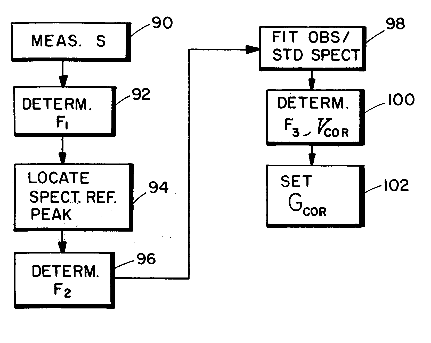
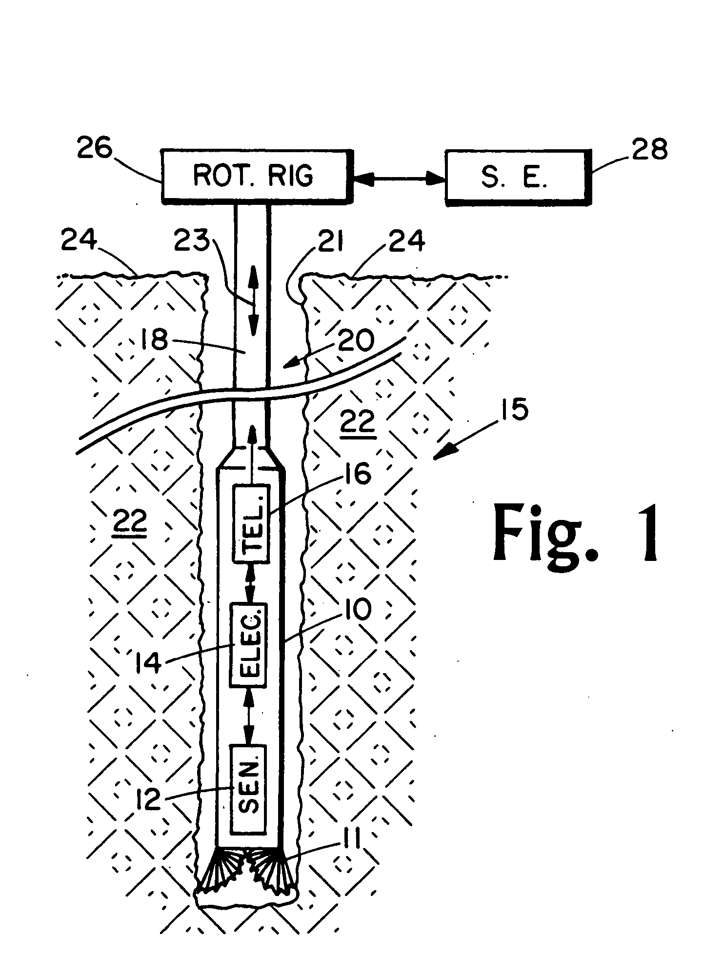
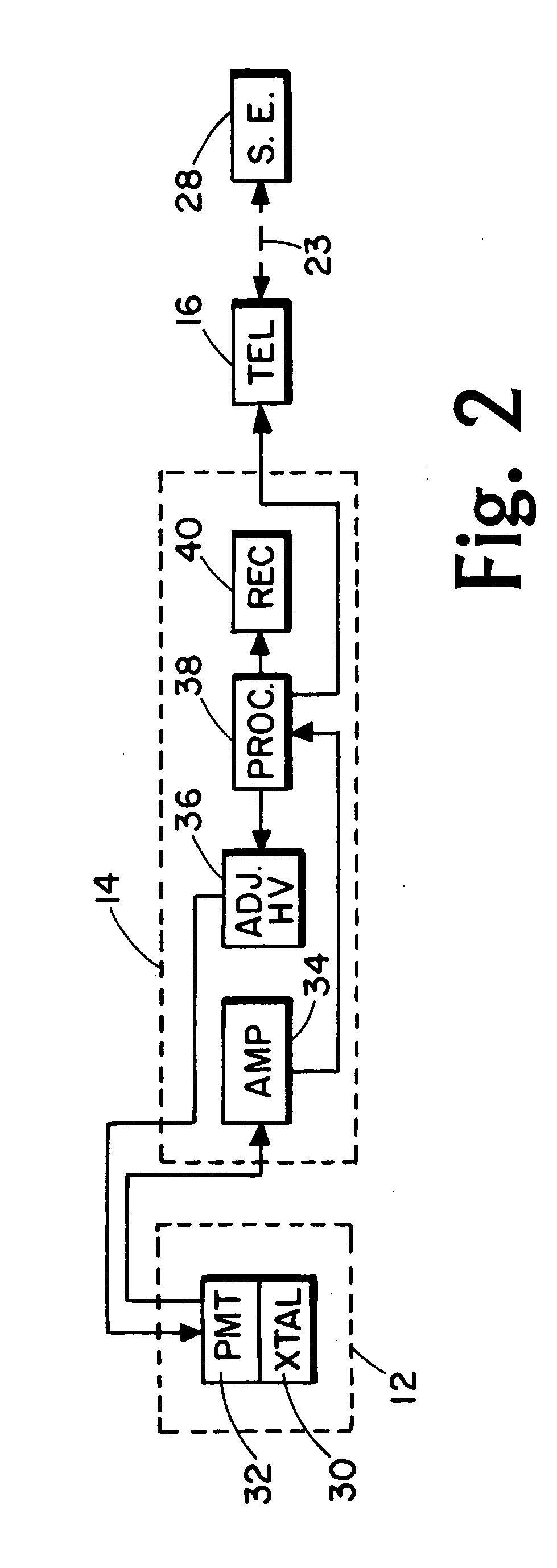
[0034] Details of the preferred embodiments of the LWD spectral gamma ray logging system are presented in sections. System hardware is first disclosed. This is followed by disclosure of methodology used to monitor measured gamma ray spectra, and to stabilize the gain of these spectra as borehole temperature varies. Two gain stabilization methods are disclosed. With both, stabilization is accomplished in real time and without operator intervention. Once gain stabilization has been obtained, methods for determining elemental concentrations of naturally occurring K, U and Th are discussed. Finally, measures of total and azimuthal concentrations of K, U and Th are discussed, and “log” presentations of these measurements are illustrated.

[0035] The invention is directed toward the measure of gamma radiation that occurs naturally in earth formation. It should be understood, however, that the basic concepts of the invention are applicable for quantitative measurements of any type of gamma ...


PUM


Abstract

A method for determining concentrations of naturally occurring radioactive elements in earth formation by analysis of gamma ray energy spectra measured by at least one gamma ray detector while the borehole is being drilled. Gain of the gamma ray detector is controlled automatically through analysis of the spectra. The one or more gamma ray detectors are disposed at the periphery of the downhole instrumentation to maximize sensitivity. Elemental concentrations of naturally occurring radioactive elements such as potassium, uranium and thorium are measured either as a function of depth in the borehole, or as a function of aximuthal sectors around the borehole wall, or as a function of both depth and azimuthal sectors.

Description

[0001] This invention is directed toward the measure of gamma radiation from earth formation penetrated by a well borehole. More particularly, the invention is directed toward the determination of concentrations of naturally occurring radioactive elements in earth formation by analysis of energy spectra measured by at least one gamma ray detector while the borehole is being drilled. BACKGROUND OF THE INVENTION [0002] The measure of naturally occurring gamma radiation as a function of depth within a well borehole is the basis of one of the earliest borehole geophysical exploration system. This type system, commonly referred to as a natural gamma ray logging system, typically comprises at least one gamma ray detector housed in a downhole tool that is conveyed along the borehole. [0003] One type of natural gamma ray logging system comprises a logging tool that is responsive to total gamma radiation emitted by the earth formation, and the tool is conveyed along the borehole by means of ...

Claims


Application Information

Patent Timeline
Patent Type & Authority Applications(United States)
IPC IPC(8): E21B49/00G01VG01V5/00G01V5/06G01V5/12G01V13/00
CPCG01V5/06G01V5/12G01V5/125
Inventor MICKAEL, MEDHAT
Owner WEATHERFORD CANADA
Why Eureka
Try Eureka