Breathing synchronized computed tomography image acquisition

a computed tomography and image acquisition technology, applied in tomography, applications, instruments, etc., can solve the problems of cardiac cycle cardiac cycle ct image generation, cardiac cycle ct image not desirable, and the quality of ct image degradation

Active Publication Date: 2005-09-15
VARIAN MEDICAL SYSTEMS
View PDF4 Cites 98 Cited by
  • Summary
  • Abstract
  • Description
  • Claims
  • Application Information

AI Technical Summary

Benefits of technology

[0008] A method for collecting CT image data includes determining a number of intervals N into which a respiratory cycle is to be divided, determining a number of respiratory cycles M to be covered in one gantry rotation, and rotating a gantry to collect at least M×N sets of CT image data of at least a portion of a patient, wherein each set of the CT image data corresponds to a phase of a respiratory cycle. In some embodiments, the method further includes repeating the step of rotating until the number of gantry rotation is at least N. The method provides a systematic process for collecting CT image data such that a complete set of data for CT image reconstruction can be collected efficiently while considering a patient's breathing.

Problems solved by technology

However, currently available computed tomographic apparatus may not be able to generate tomographic images with sufficient quality or accuracy due to physiological movement of a patient.
For example, beating of a human heart and breathing have been known to cause degradation of quality in CT images.
However, such method does not generate desirable CT images for a portion of a cardiac cycle when the heart's motion exceeds the threshold level.
Degradation of quality of CT images due to patient's breathing is more difficult to address than that associated with heart motion.
Patients' breathing poses a unique problem to CT imaging that is different from heart motion.
This is because the pattern and the period of a patient's breathing cycle is generally less consistent when compared to those of the patient's cardiac cycle.
As such, while a particular phase of a cardiac cycle may be predicted with sufficient accuracy, a particular phase of a breathing cycle may not be as easily predicted or determined.
However, collecting a large quantity of CT image data sufficient for forming a video while considering breathing motion may take a much longer time.
This may cause a patient who is confined within a gantry opening to feel uncomfortable and subject the patient to excessive radiation.

Method used


Image

  • Breathing synchronized computed tomography image acquisition
  • Breathing synchronized computed tomography image acquisition
  • Breathing synchronized computed tomography image acquisition

Examples


Embodiment Construction

[0025] Various embodiments of the present invention are described hereinafter with reference to the figures. It should be noted that the figures are not drawn to scale and elements of similar structures or functions are represented by like reference numerals throughout the figures. It should also be noted that the figures are only intended to facilitate the description of specific embodiments of the invention. They are not intended as an exhaustive description of the invention or as a limitation on the scope of the invention. In addition, an aspect described in conjunction with a particular embodiment of the present invention is not necessarily limited to that embodiment and can be practiced in any other embodiments of the present invention.

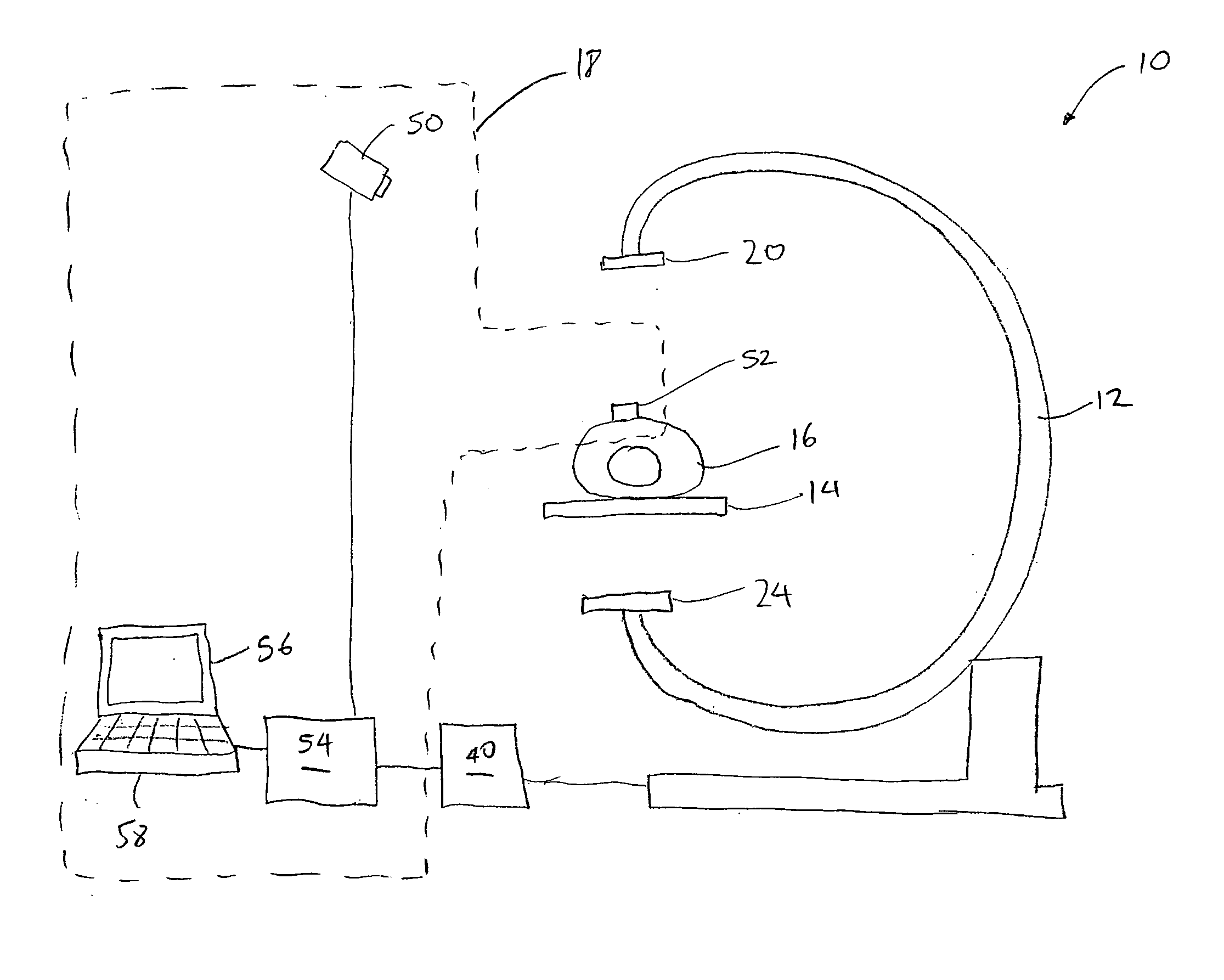
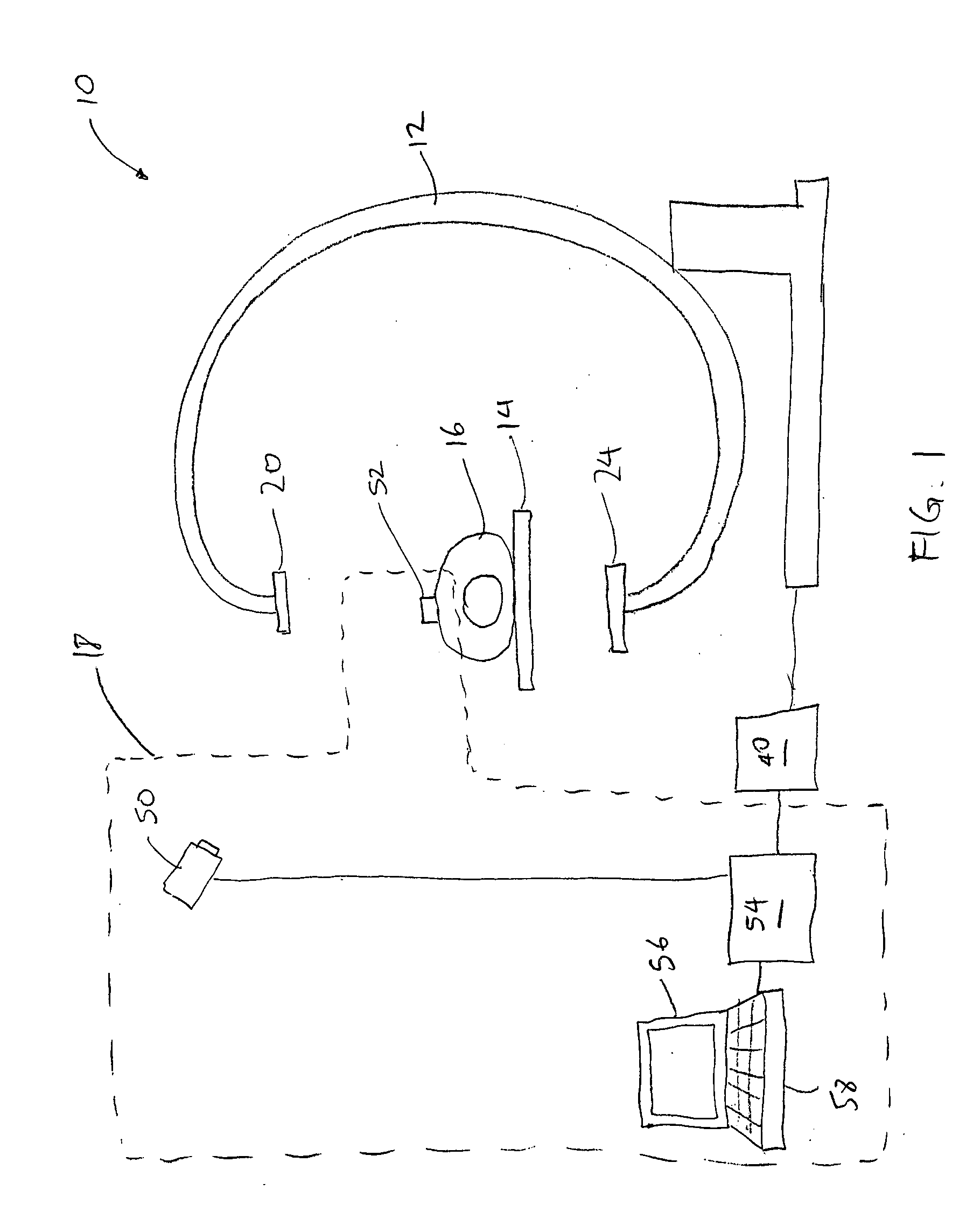
[0026] Referring now to the drawings, in which similar or corresponding parts are identified with the same reference numeral, FIG. 1 illustrates a computed tomography image acquisition system 10 in accordance with an embodiment of the present in...


PUM

PropertyMeasurementUnit
anglesaaaaaaaaaa
timeaaaaaaaaaa
phase anglesaaaaaaaaaa

Abstract

A method for collecting computed tomography (CT) image data includes determining a number of intervals N into which a respiratory cycle is to be divided, determining a number of respiratory cycles M to be covered in one gantry rotation, and rotating a gantry to collect at least M×N sets of CT image data of at least a portion of a patient, wherein each set of the CT image data corresponds to a phase of a respiratory cycle.

Description

BACKGROUND OF THE INVENTION [0001] 1. Field of the Invention [0002] This invention relates generally to systems and methods for image acquisition and, more specifically, to systems and methods for collecting computed tomography (CT) image data and reconstructing CT images. [0003] 2. Background of the Invention [0004] Computed tomography is an imaging technique that has been widely used in the medical field. In a procedure for computed tomography, an x-ray source and a detector apparatus are positioned on opposite sides of a portion of a patient under examination. The x-ray source generates and directs a x-ray beam towards the patient, while the detector apparatus measures the x-ray absorption at a plurality of transmission paths defined by the x-ray beam during the process. The detector apparatus produces a voltage proportional to the intensity of incident x-rays, and the voltage is read and digitized for subsequent processing in a computer. By taking a plurality of readings from mu...

Claims


Application Information

Patent Timeline
Patent Type & Authority Applications(United States)
IPC IPC(8): A61B5/113A61B6/00A61B6/03G01N23/00G21K1/12H05G1/60
CPCA61B5/1135A61B5/7289A61B6/541A61B6/4441A61B6/032
Inventor MOSTAFAVI, HASSANSEPPI, EDWARD J.PARTAIN, LARRY
Owner VARIAN MEDICAL SYSTEMS
Why Eureka
Try Eureka