

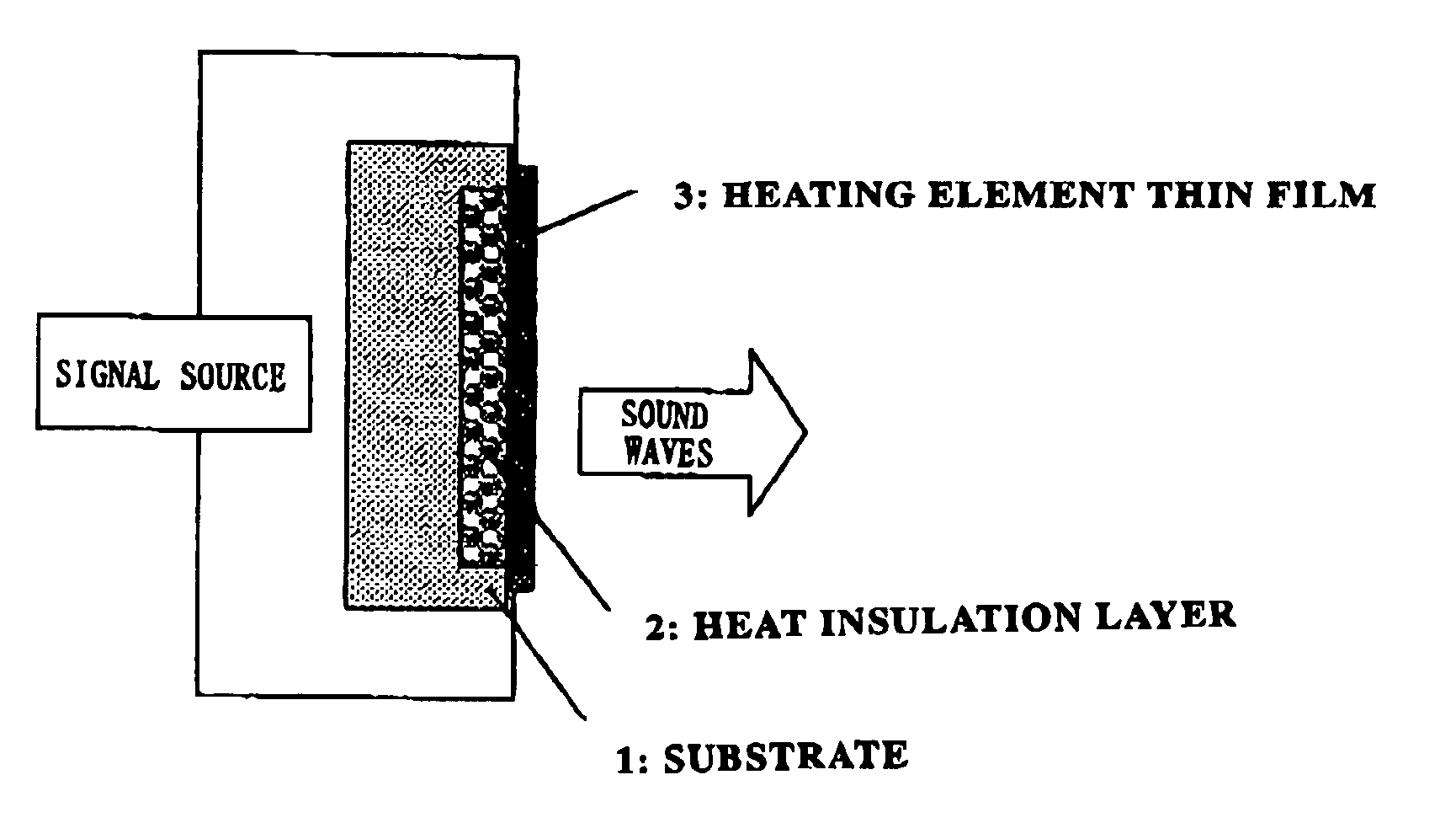
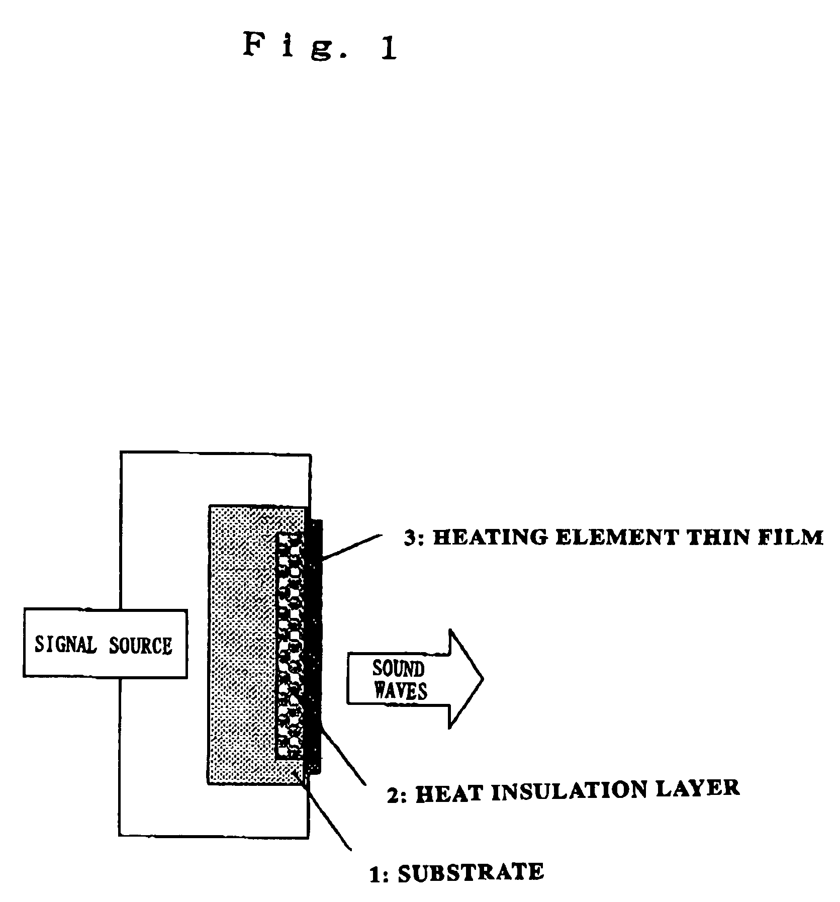
Thermally excited sound wave generating device
a sound wave generation and thermal energy technology, applied in the direction of transducer details, mechanical vibration separation, instruments, etc., can solve the problems of increasing the joule heat generated by an increase in input power, difficulty in fine-tuning and arraying the sound generating device, and no real prospects for performance improvemen
- Summary
- Abstract
- Description
- Claims
- Application Information
AI Technical Summary
Benefits of technology
Problems solved by technology
Method used
Image

Examples
first embodiment
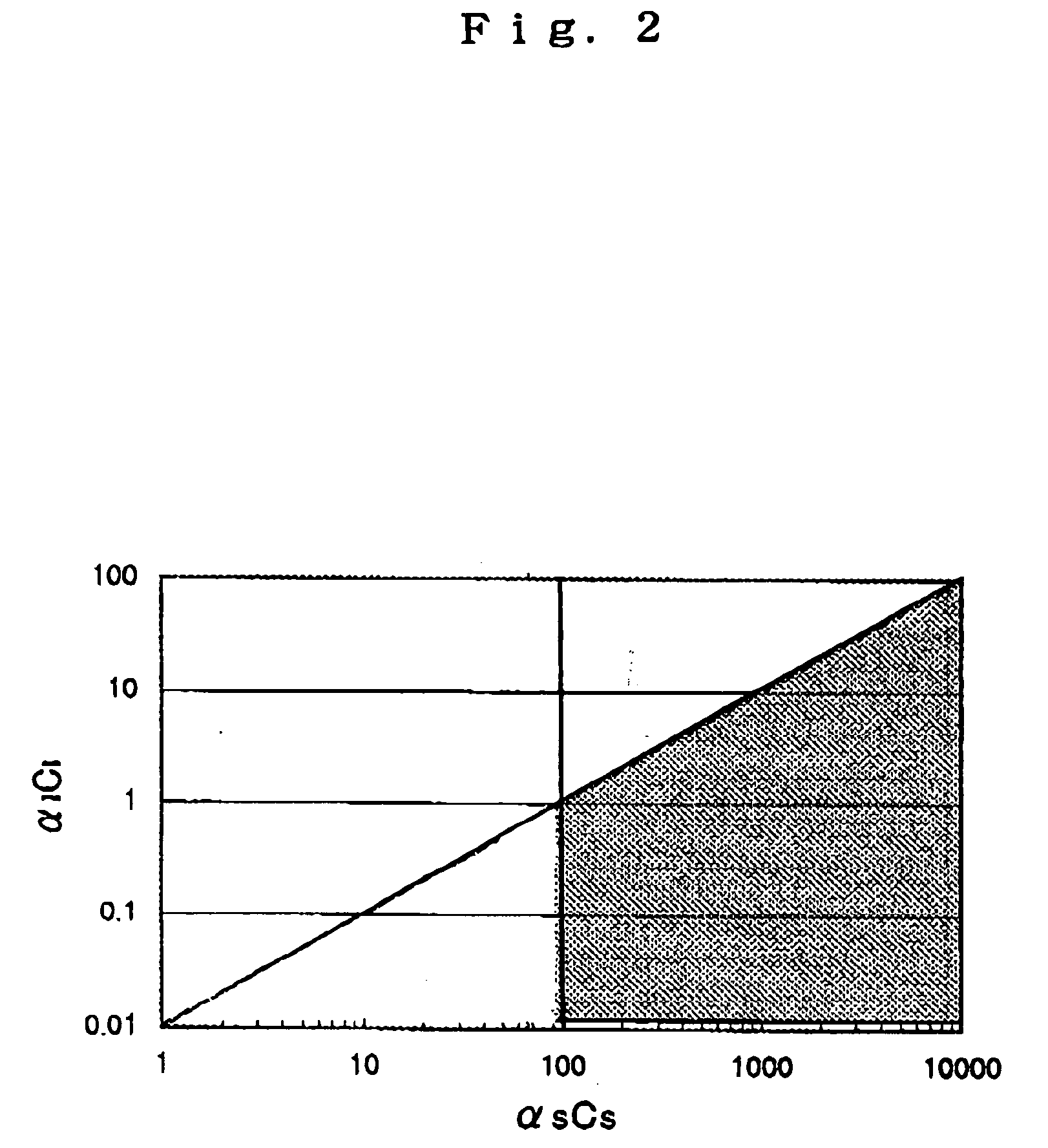
[0037] A film of Al was formed 300 nm as a contact electrode for anodic oxidation treatment on a rear surface of a P-type (100) single crystalline silicon substrate (80 to 120 Ωcm) (αSCS=286×106) according to vacuum evaporation. Thereafter, this substrate was subjected to the anodic oxidation treatment at a current density of 100 mA / cm2 for eight minutes with platinum as a counter electrode in a solution of HF(55%):EtOH-1:1 to form a porous silicon layer (αICI=0.06×10⁶) with a thickness of about 50 μm. Finally, W was formed in a thickness of 50 nm as a heating element thin film on the porous silicon layer according to the sputtering method to manufacture an element with an area of 5 mm2.
second embodiment
[0038] A layer (αICI=0.26×10⁶) coated with polyimide in a thickness of 50 μm was formed on an upper surface of a substrate of pure copper (thickness 1 mm) (αSCS=1393×106). Finally, W was formed in a thickness of 50 nm as a heating element thin film on the polyimide according to the sputtering method to manufacture an element with an area of 5 mm2.
third embodiment
[0039] An SiO2 layer (αICI=3.2×10⁶) with a thickness of 2 μm was formed on an upper surface of a substrate of pure copper (thickness 1 mm) (αSCS=1393×106) according to the sputtering method. Finally, W was formed in a thickness of 50 nm as a heating element thin film on the SiO2 according to the sputtering method to manufacture an element with an area of 5 mm2.
PUM
 Abstract
Description
Claims
Application Information