Dispensing and injection system for radiopharmaceuticals

a technology of radiopharmaceuticals and injection systems, which is applied in the field of medicine dispensing and injection systems, can solve the problems of medical employees still being subject to radiation, major protection challenges, and serious health hazards, and achieve excellent radiation protection and easy automatic control

Inactive Publication Date: 2005-09-15
SHIH CHI DAU
View PDF6 Cites 133 Cited by
  • Summary
  • Abstract
  • Description
  • Claims
  • Application Information

AI Technical Summary

Benefits of technology

[0015] Thus, compared to the prior art, the present invention effectively overcomes the problems of inconvenience and poor safety occurring in handling radiopharmaceuticals whereby the radiopharmaceuticals dispensing a

Problems solved by technology

Thus, it is a major challenge to protect the radio-chemists and medical employees from over-exposure to radiation.
If they are not properly protected from radiation, then their health is subject to serious hazard.
However, even the radiopharmaceuticals is accommodated in a lead canister, medical employees are still subject to radiation during the process of retrieving, disposing, quantity measurement, quality control and injection of the radiopharmaceuticals.
Further, since the radiation energy of PET radiopharmaceuticals is very high, a very heavy lead canister must be used, which causes a serious burden to the medical employees.
Although a variety of conventional devices are designed to control radiation contamination of the radiopharmaceuticals, these devices are only of limited effectiveness.
However, in practical applications, an operator for retrieva

Method used


Image

  • Dispensing and injection system for radiopharmaceuticals
  • Dispensing and injection system for radiopharmaceuticals
  • Dispensing and injection system for radiopharmaceuticals

Examples


Embodiment Construction

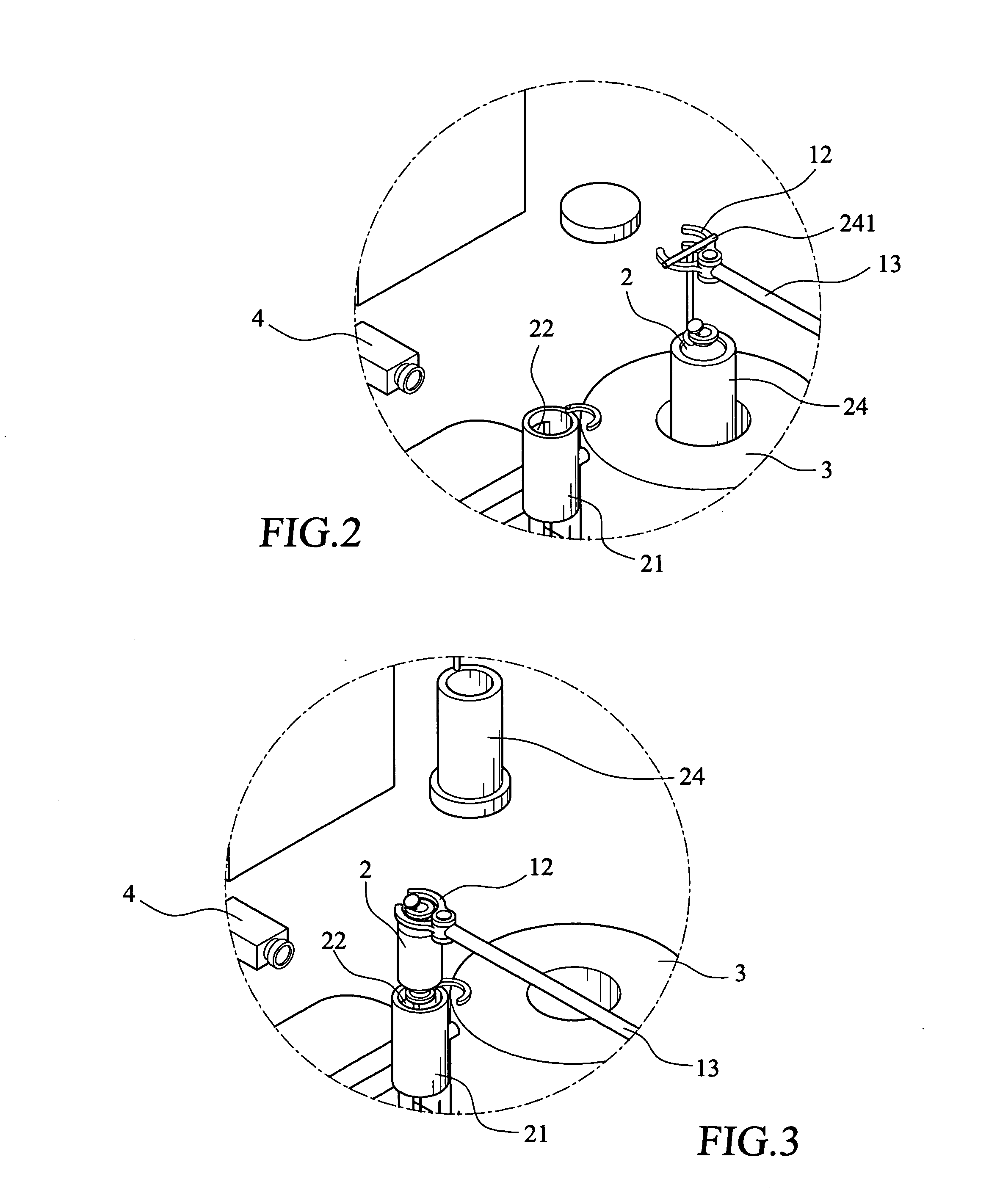
[0032] With reference to FIG. 1, which shows a front-side perspective view of a radiation-safe radiopharmaceuticals dispensing and injection system constructed in accordance with the present invention, as shown in the drawing, the present invention comprises a radiation-shielded hermetic chamber 1, which is made of materials having radiation-shielding function, such as lead and tungsten. The radiation-shielded hermetic chamber 1 provides a closed, radiation-shielded interior space, and the hermetic chamber is provided with at least one injection needle insertion hole 11.

[0033] The radiation-shielded hermetic chamber 1 receives a vial 2 (also referring to FIGS. 2 and 3), which contains radiopharmaceuticals. The vial 2 can be handled by a robotic manipulating clamp 12 to move into a vial container 21. The manipulating clamp 12 comprises an extension bar 13, which allows the manipulating clamp 12 to extend into the hermetic chamber 1 and serve as a tool for manual operation. Of course...


PUM


Abstract

Disclosed is a dispensing and injection system for radiopharmaceuticals, wherein a dosage calibrator is arranged inside a radiation-shielded hermetic chamber for detecting the radioactivity of radiopharmaceuticals contained in a vial. At least one saline water cartridge is arranged inside the casing and includes an internal passage, radiopharmaceuticals discharge end, a radiopharmaceuticals injection end, a and saline water reservoir outlet end. The saline water cartridge forms a saline water reservoir. A movable dispensing and injection mechanism controls radiopharmaceuticals dispensing operation of a syringe and controls movement of the syringe between a radiopharmaceuticals dispensing position and an injection position. When the movable dispensing and injection mechanism moves the syringe to the radiopharmaceuticals dispensing position, the syringe withdraws a predetermined amount of radiopharmaceuticals from the vial. When moved to the injection position, the syringe injects the withdrawn radiopharmaceuticals into the radiopharmaceuticals injection end of the saline water cartridge. After the radiopharmaceuticals is injected into a patient, the saline water stored in the saline water reservoir of the saline water cartridge is withdrawn for effecting flushing process.

Description

FIELD OF THE INVENTION [0001] The present invention relates generally to a medicine dispensing and injection system, and in particular to radiation-shielded dispensing and injection system for radiopharmaceuticals. BACKGROUND OF THE INVENTION [0002] Due to the unique invivo imaging capability, positron emission tomography (PET) has been recently used in early detection and treatment of cancers that could not be detected previously. This makes PET one of most important measures for diagnosis of a variety of tumors, as well as the main stream of future nuclear medicine [0003] Positron radio-nuclides (radiopharmaceuticals) for PET are generated in a cyclotron, which are then composed with other elements to form compound / molecules, such as glucose, amino acid, and water by radio-chemist and conveyed to injection room for injection into human body by medical employees in order to carry out PET diagnosis by doctors. The positrons are annihilated with electrons inside the human body, which...

Claims


Application Information

Patent Timeline
IPC IPC(8): A61J3/00A61K51/00A61M36/14
CPCA61M5/007A61M2209/08A61M5/1407
Inventor MUTO, AKIOHU, CHI-MIN
Owner SHIH CHI DAU
Why Eureka
Try Eureka