[0012] A sixth object of the present invention is to provide an improved corneal marking device configured to accurately mark positions on the surface of the cornea in a highly reproducible manner from procedure to procedure, and from patient to patient.
[0015] The corneal marking device according to the present invention can be made entirely, or portions thereof, from a wide variety of materials, including plastic,
metal, composite, glass,
ceramic, or other suitable materials. The corneal marking device according to the present invention is preferably made from a plastic material, in particular a transparent plastic material and configured to allow an
eye surgeon to view through the template or marking end portion of the device during use. Preferred plastics include poly
carbonate, poly
styrene, poly theromide resins, or other suitable plastic resin blends. Preferably, the corneal marking device according to the present invention is disposable, and for one time use. The corneal marking device according to the present invention is preferably made by a
plastic injection molding process using a carefully machined and highly accurate and precise mold cavity to provide high accuracy, and reproduce ability of corneal marking results from procedure to procedure and eye to eye.
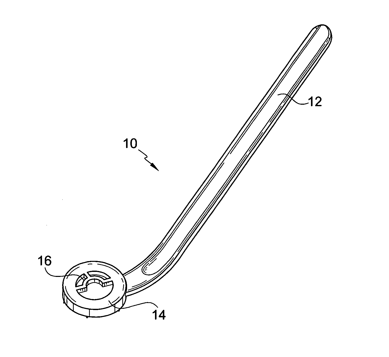
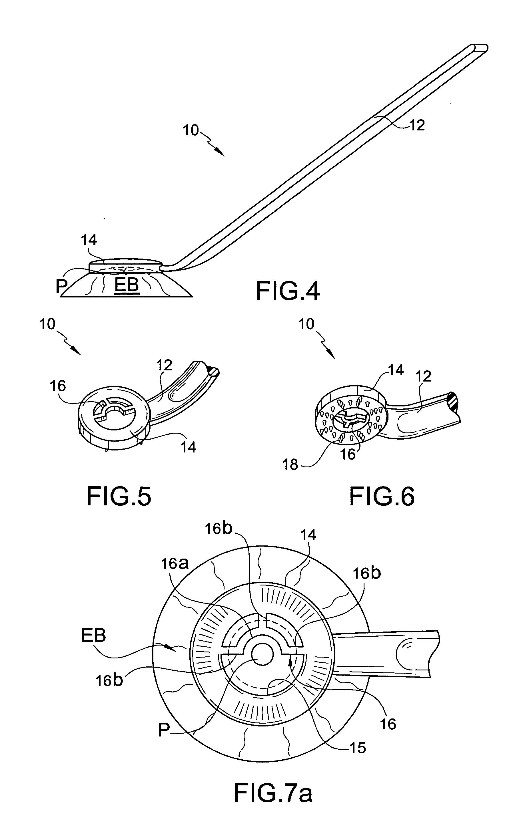
[0016] The corneal marking device according to the present invention is provided with one or more protrusions configured to make a temporary indent, preferably a temporary
dimple, and provide temporary markings or a pattern of markings on the surface of the cornea by application of pressure. For example, the tips of the protrusions are configured (e.g. contoured, shaped, textured and / or finished) so that when pressure is applied to the corneal marking device the protrusions of the corneal marking device press against the surface of the eye. The tips of the protrusions make indents, preferably dimples, that temporary mark the surface of the eye. The indenting or dimpling
process changes the angle of reflection of light hitting the indents or dimples verses the surrounding tissue, which can be visually detected by the
eye surgeon, especially with magnified vision using a loop or
microscope. In a short amount of time (e.g. less than 10 minutes or even less than 4 minutes), these indents or dimples dissipate (i.e. heal) and the markings created thereby visually disappear.
[0017] The tips of the protrusions are preferably shaped, contoured, textured and / or finished so as not to penetrate,
cut, scratch, or otherwise compromise or damage the surface of the cornea, but instead only provide temporary marks on the surface of the cornea. Specifically, in some embodiments, the protrusions are configured so that the marks last approximately less than 10 minutes from the time of the application of pressure from the protrusions against the surface of the cornea of the eye. This allows enough time for the
eye surgeon to conduct the surgical procedure such as conductive keratoplasty.
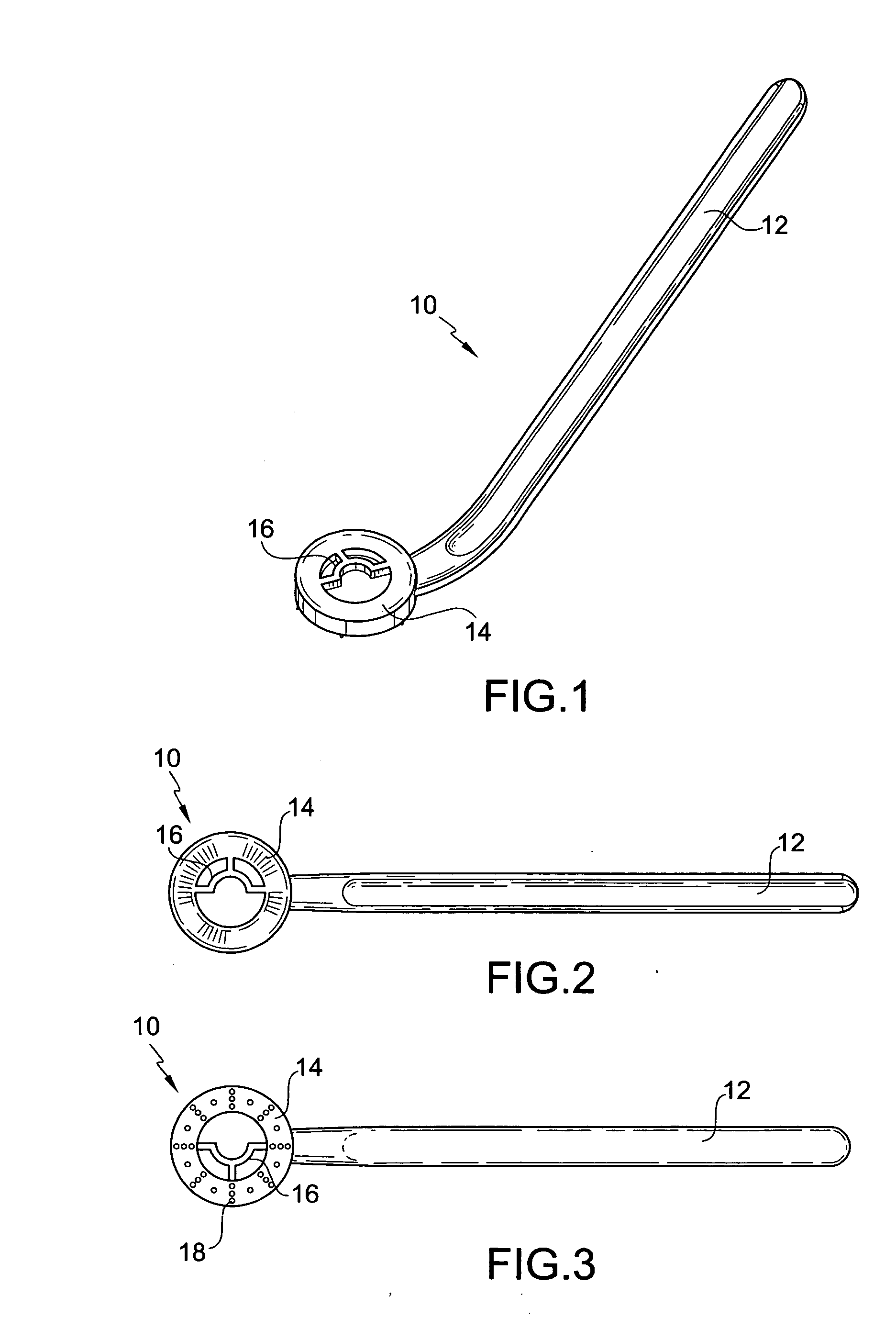
[0019] Preferred embodiments of the corneal marking device according to present invention utilize a plurality of protrusions arranged in a particular pattern. In a preferred embodiment, multiple sets (e.g. eight (8) sets) of three (3) protrusions are provided on a ring-shaped template end portion of the corneal marking device. The sets of three (3) protrusions are each oriented along radii extending from the center of the cornea (i.e. center of
pupil). Further, for example, the multiple sets of three (3) protrusions are equally spaced apart around an arc disposed within the dimensions of the cornea, and centered off the center of the cornea. Further, the individual respective protrusions of the multiple sets of three (3) protrusions are located on three (3) separate arcs disposed within the dimensions of the cornea, which arcs are centered off the center of the cornea. The three (3) separate arcs are located at three (3) different
radius (e.g. 6 mm, 7 mm and 8 mm) from the center of the cornea. Additional single protrusions can be provided between these sets of three (3) protrusions to provide incremental markings to 1) facilitate marking for astigmatic correction; and 2) allow the eye surgeon to more accurately judge distances between the sets of three (3) protrusions for placement of the conductive keratoplasty tip during conductive keratoplasty.

