

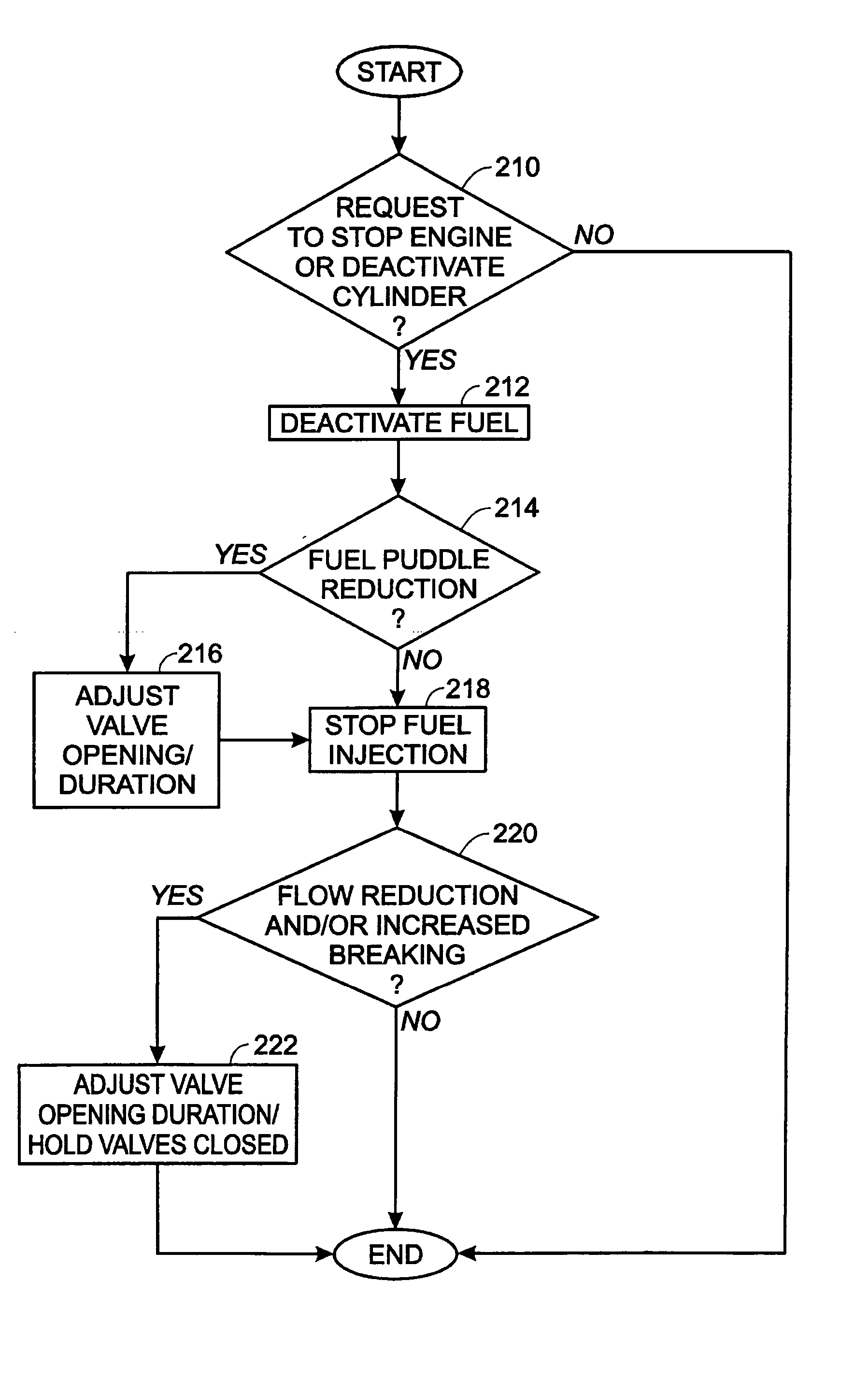
Engine shut-down for engine having adjustable valve timing
- Summary
- Abstract
- Description
- Claims
- Application Information
AI Technical Summary
Benefits of technology
Problems solved by technology
Method used
Image

Examples
Embodiment Construction
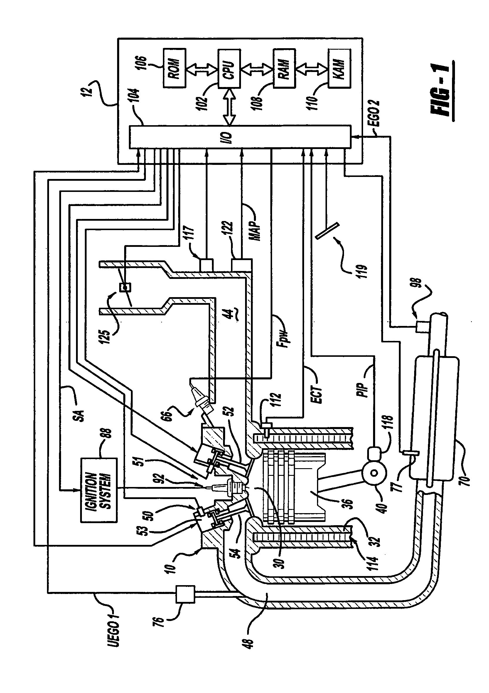
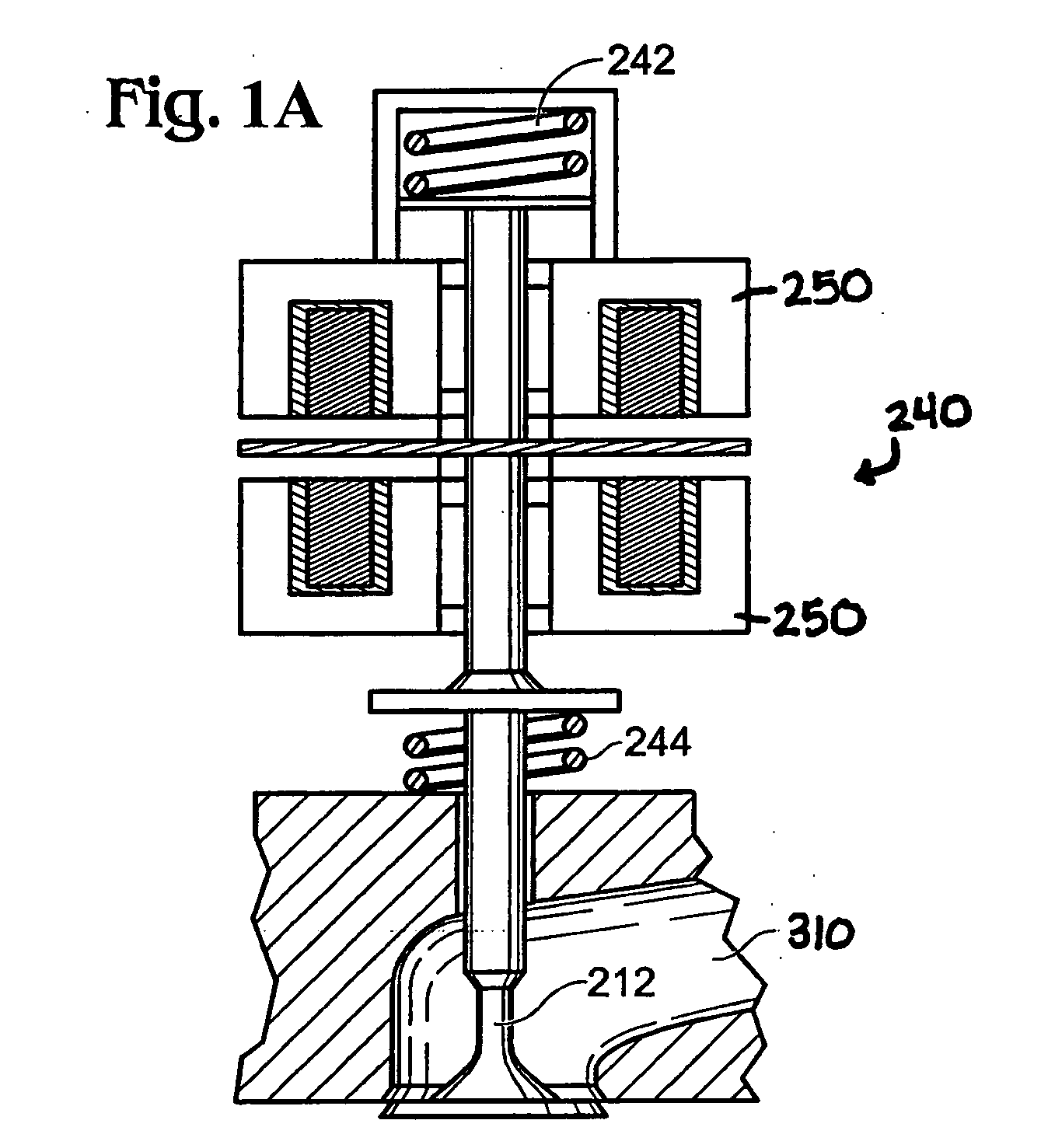
[0011] Referring to FIG. 1, internal combustion engine 10, comprising a plurality of cylinders, one cylinder of which is shown in FIG. 1, is controlled by electronic engine controller 12. Engine 10 includes combustion chamber 30 and cylinder walls 32 with piston 36 positioned therein and connected to crankshaft 40. Combustion chamber 30 is shown communicating with intake manifold 44 and exhaust manifold 48 via respective intake valve 52 an exhaust valve 54. Each intake and exhaust valve is operated by an electromechanically controlled valve coil and armature assembly 53, such as shown in FIG. 1A. Armature temperature is determined by temperature sensor 51. Valve position is determined by position sensor 50. In an alternative example, each of valves actuators for valves 52 and 54 has a position sensor and a temperature sensor.
[0012] Intake manifold 44 is also shown having fuel injector 66 coupled thereto for delivering liquid fuel in proportion to the pulse width of signal FPW from ...
PUM
 Abstract
Description
Claims
Application Information