LPP EUV light source

a light source and euv technology, applied in the field of euv light sources, can solve the problems of not teaching or suggesting, however, any optimization, and difficulty in getting an output pulse of such short duration, and achieve the effects of increasing conversion efficiency, high conversion efficiency, and effective and efficient operation

Inactive Publication Date: 2005-09-22
ASML NETHERLANDS BV
View PDF76 Cites 128 Cited by
  • Summary
  • Abstract
  • Description
  • Claims
  • Application Information

AI Technical Summary

Problems solved by technology

They do not teach or suggest, however, any optimization, e.g., of an energy conversion efficiency, e.g., for use in producing EUV light with short duration drive laser pulses.
They also do not teach or suggest, e.g., the use of this method for a drive laser for laser-produced plasmas.
Because, e.g., the KrF excimer laser has an upper state KrF* of the KrF laser transition on the order of 12 ns, it is difficult to get an output pulse of such short duration and in fact difficult to get much below 15-20 ns with state of the art KrF gas discharge lasers, without having to tolerate a significant loss in output power.

Method used


Image

  • LPP EUV light source
  • LPP EUV light source
  • LPP EUV light source

Examples


Embodiment Construction

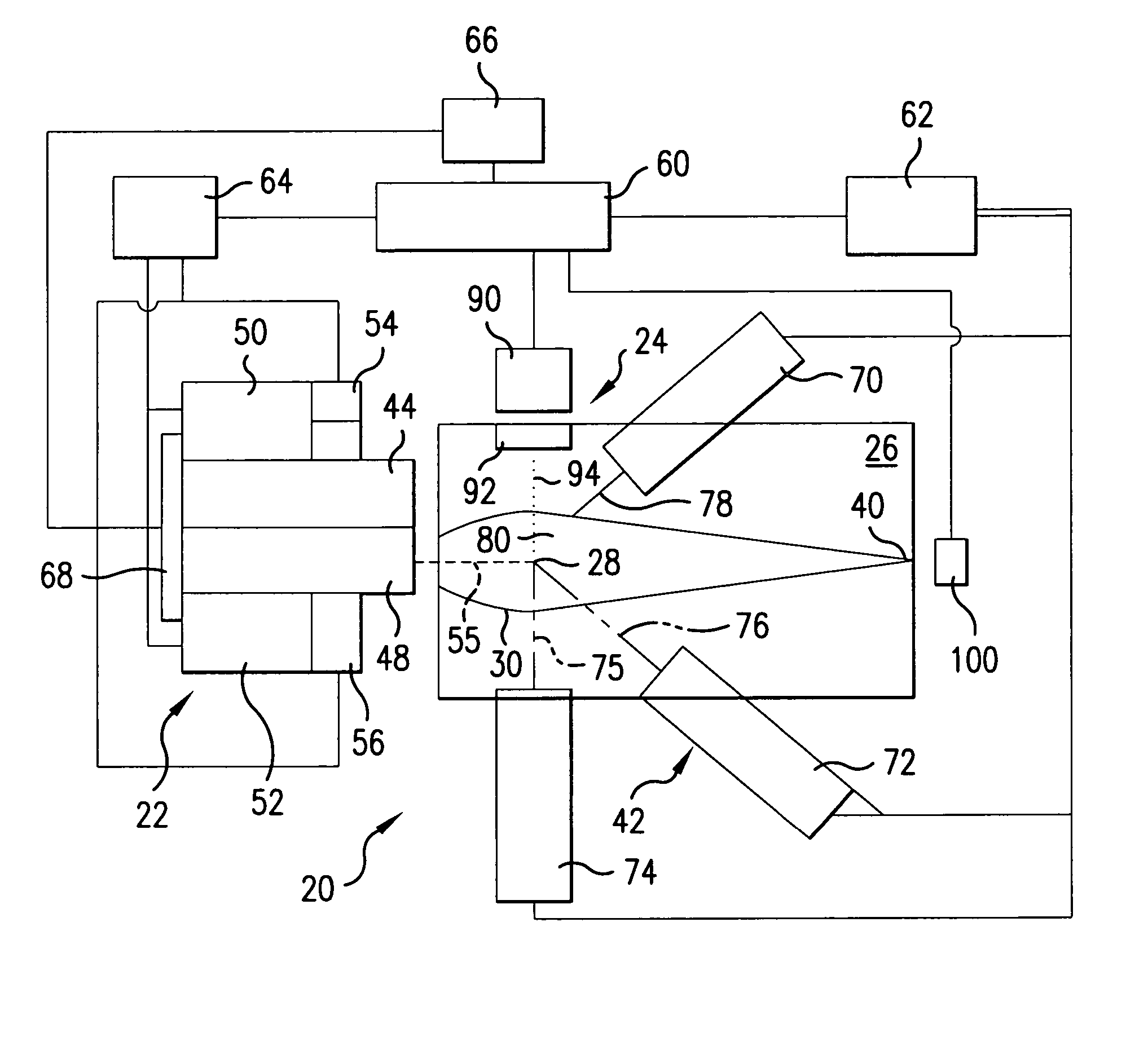
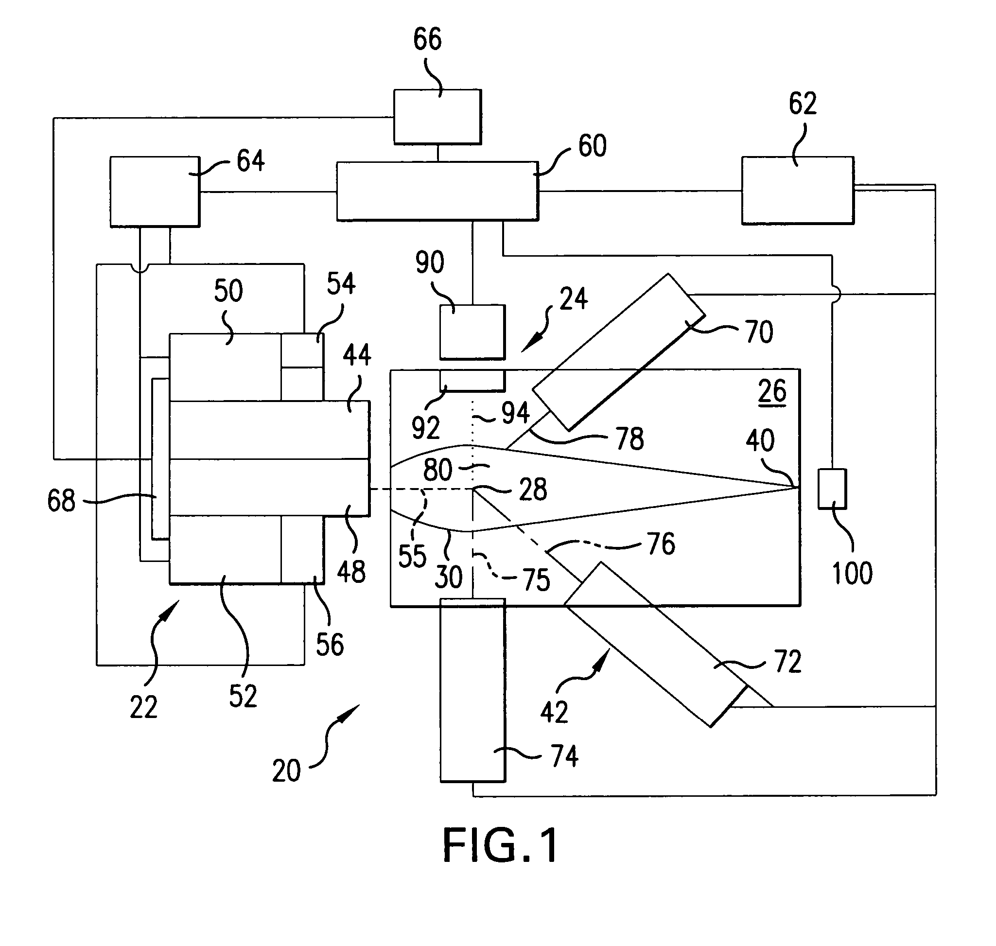
[0042] Turning now to FIG. 1 there is shown a schematic view of an overall broad conception for an EUV light source, e.g., a laser produced plasma EUV light source 20 according to an aspect of the present invention. The light source 20 may contain a pulsed laser system 22, e.g., a gas discharge excimer or molecular fluorine laser operating at high power and high pulse repetition rate and may be a MOPA configured laser system, e.g., as shown in U.S. Pat. Nos. 6,625,191, 6,549,551, and 6,567,450. The light source 20 may also include a target delivery system 24, e.g., delivering targets in the form of liquid droplets, solid particles or solid particles contained within liquid droplets. The targets may be delivered by the target delivery system 24, e.g., into the interior of a chamber 26 to an irradiation site 28, otherwise known as an ignition site or the sight of the fire ball, which is where irradiation by the laser causes the plasma to form from the target material. Embodiments of t...


PUM

PropertyMeasurementUnit
wavelengthaaaaaaaaaa
center wavelengthsaaaaaaaaaa

Abstract

An apparatus and method is described for effectively and efficiently providing plasma irradiation laser light pulses in an LPP EUV light source which may comprise a laser initial target irradiation pulse generating mechanism irradiating a plasma initiation target with an initial target irradiation pulse to form an EUV generating plasma having an emission region emitting in-band EUV light; a laser plasma irradiation pulse generating mechanism irradiating the plasma with a plasma irradiation pulse after the initial target irradiation pulse so as to compress emission material in the plasma toward the emission region of the plasma. The plasma irradiation pulse may comprise a laser pulse having a wavelength that is sufficiently longer than a wavelength of the initial target irradiation pulse to have an associated lower critical density resulting in absorption occurring within the plasma in a region of the plasma defined by the wavelength of the plasma irradiation pulse sufficiently separated from an initial target irradiation site to achieve compression of the emission material, and the may compress the emission region. The laser plasma irradiation pulse may produce an aerial mass density in the ablating cloud of the plasma sufficient to confine the favorably emitting plasma for increased conversion efficiency. The deposition region for the plasma irradiation pulse may be is removed enough from the initial target surface so as to insure compression of the favorably emitting plasma. A high conversion efficiency laser produced plasma extreme ultraviolet (“EUV”) light source may comprise a laser initial target irradiation pulse generating mechanism irradiating a plasma initiation target with a target irradiation pulse to form an EUV generating plasma emitting in-band EUV light; a plasma tamper substantially surrounding the plasma to constrain the expansion of the plasma.

Description

RELATED APPLICATIONS [0001] The present invention is as continuation in part of U.S. co-pending patent application Ser. No. 10 / 803,526, filed on Mar. 17, 2004, entitled, A HIGH REPETITION RATE LASER PRODUCED PLASMA EUV LIGHT SOURCE, Attorney Docket No. 2003-0125, which is assigned to the common assignee of the present application, the disclosure of which is hereby incorporated by reference. This application is related to U.S. patent application Ser. No. 10 / 409,254, entitled EXTREME ULTRAVIOLET LIGHT SOURCE, filed on Apr. 8, 2003, Attorney Docket No. 2002-0030-01, and Ser. No. 10 / 798,740, entitled COLLECTOR FOR EUV LIGHT SOURCE, filed on Mar. 10, 2004, Attorney Docket No. 2003-0083-01, and Ser. No. 10 / 615,321, entitled A DENSE PLASMA FOCUS RADIATION SOURCE, filed on Jul. 7, 2003, Attorney docket No. 2003-0004-01, and Ser. No. 10 / 742,233, entitled DISCHARGE PRODUCED PLASMA EUV LIGHT SOURCE, filed on Dec. 18, 2003, Attorney docket No. 2003-0099-01, and Ser. No. 10 / 442,544, entitled A D...

Claims


Application Information

Patent Timeline
Patent Type & Authority Applications(United States)
IPC IPC(8): G01J1/00G03F7/20H01J65/04H05G2/00
CPCB82Y10/00H05G2/008H05G2/003G03F7/70033G01J1/00G03F7/20H01J35/20H01J65/04
Inventor PARTLO, WILLIAM N.BROWN, DANIEL J. W.FOMENKOV, IGOR V.BOWERING, NORBERT R.RETTIG, CURTIS L.MACFARLANE, JOSEPHERSHOV, ALEXANDER I.HANSSON, BJORN A. M.
Owner ASML NETHERLANDS BV
Why Eureka
Try Eureka