Semiconductor device
a technology of semiconductor devices and devices, applied in semiconductor devices, semiconductor/solid-state device details, electrical apparatus, etc., can solve the problems of deteriorating interconnect or similar integration density, reduced effective use area of elements, so as to improve interconnect density, high speed operability of elements, and effective utilization of upper regions
- Summary
- Abstract
- Description
- Claims
- Application Information
AI Technical Summary
Benefits of technology
Problems solved by technology
Method used
Image
Examples
first embodiment
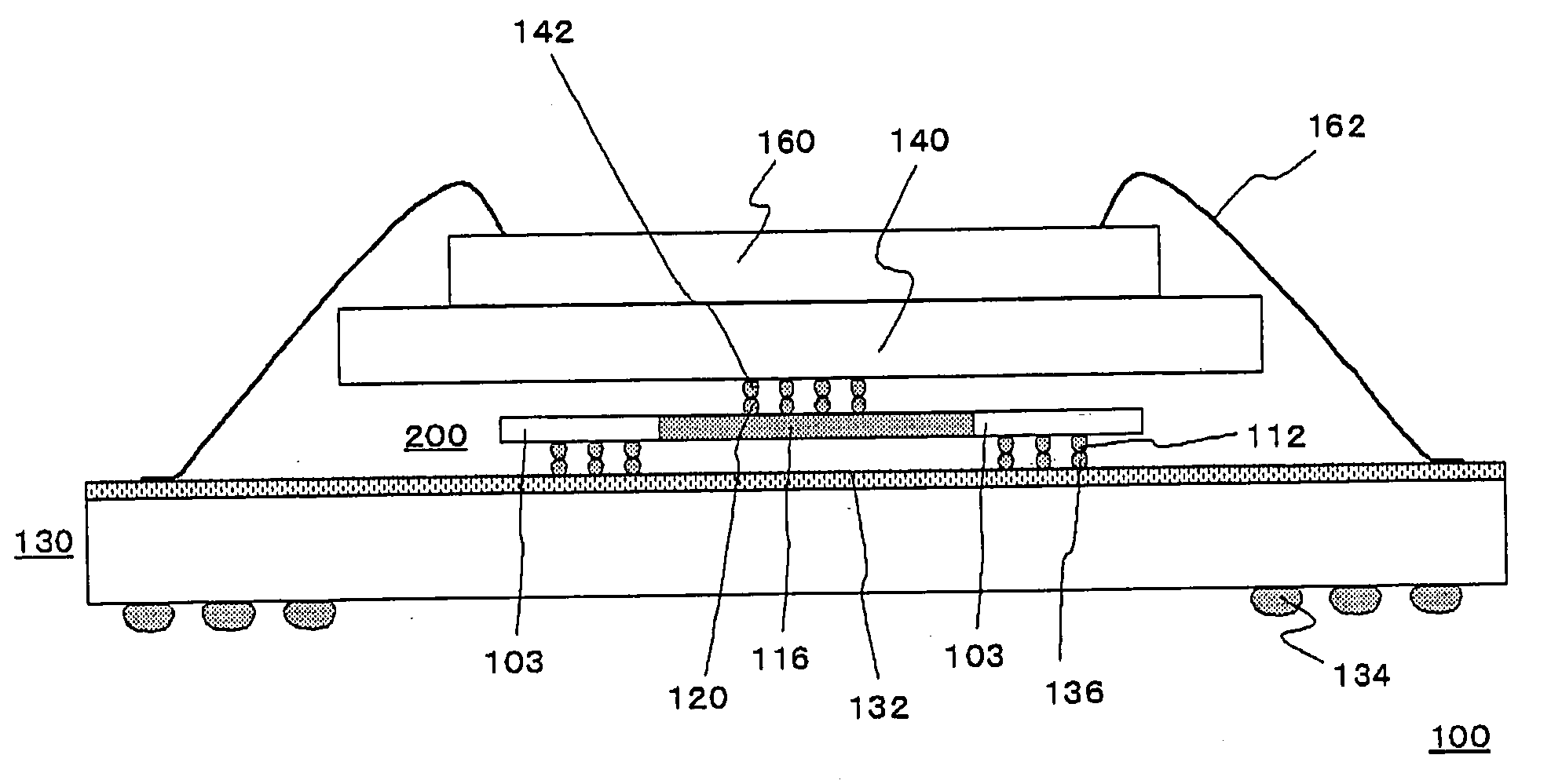
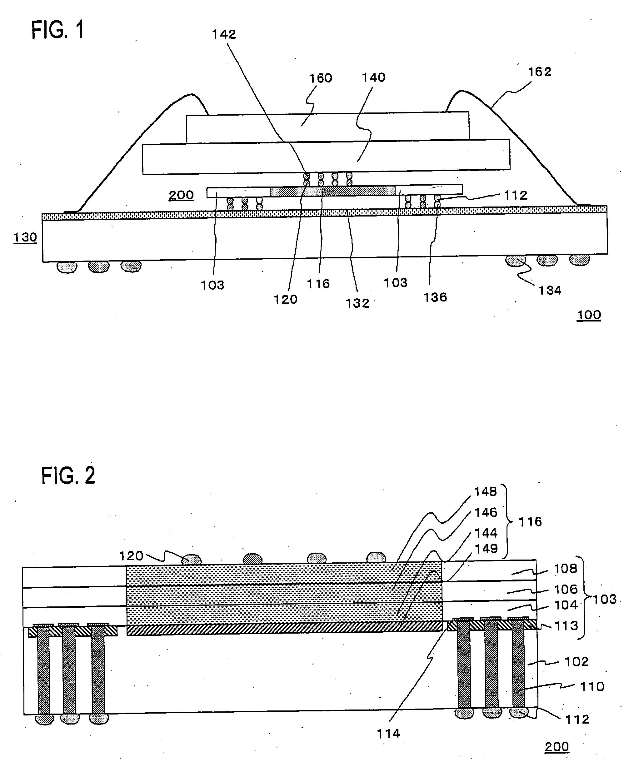
[0028]FIG. 1 is a cross-sectional view showing a configuration of a semiconductor package 100 according to the present embodiment.
[0029] The semiconductor package 100 is composed of a package substrate 130 as a circuit substrate, the logic chip 200, the DRAM 140, and a flash memory 160. Here, the front surface of the package substrate 130 is provided with an interconnect layer 132, and the rear surface of the package substrate 130 is provided with a bump 134. In addition, the interconnect layer 132 provided for the package substrate 130 is electrically connected to the logic chip 200 via the through electrode 110 or the like, which is described later. The logic chip 200 is electrically connected to the DRAM 140 via the bump 120 and a bump 142. Here, the bump 120 is mounted on the top of a logic circuit 116, which is described later. The flash memory 160 is mounted on the DRAM 140, and the flash memory 160 is electrically connected to the interconnect layer 132 provided for the pack...
second embodiment
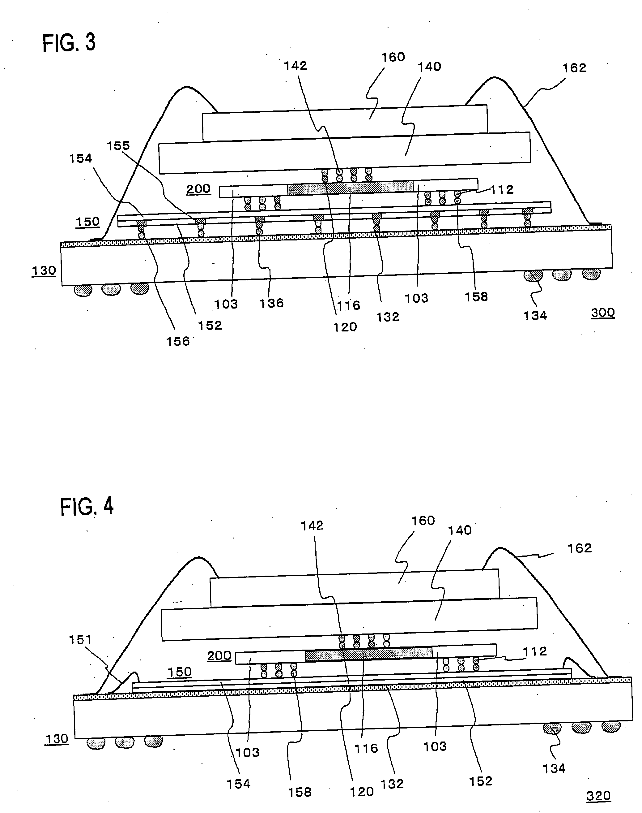
[0040] In the first embodiment, a configuration is that the interconnect layer 132 provided on the package substrate 130 is electrically connected to the logic chip 200 via the bump 136 and the bump 112, however, an interposer 150 may be provided between the package substrate 130 and the logic chip 200.
[0041]FIG. 3 is a cross-sectional view showing a configuration of a semiconductor package 300 according to the present embodiment.
[0042] The interconnect layer 132 provided on the package substrate 130 is electrically connected to the interposer150 via the bump 136 provided on the front surface of the interconnect layer 132 and a bump 156 provided on a rear surface of a substrate 152 of the interposer 150. In addition, a through electrode 155 penetrates the substrate 152 of the interposer 150, and is electrically connected to an interconnect layer 154 of the interposer 150.
[0043] The interposer 150 is electrically connected to the logic chip 200 via a bump 158 provided on the front...
third embodiment
[0048] In the first embodiment and the second embodiment, the configuration is that the DRAM 140 is mounted on the logic chip 200, however, a configuration may also be suitable that the DRAM 140 is mounted on the package substrate 130 and the logic chip 200 is mounted on the DRAM 140.
[0049]FIG. 5 is a cross-sectional view showing a configuration of a semiconductor package 340 according to the present embodiment.
[0050] The DRAM 140 is mounted on the package substrate 130, the logic chip 200 is mounted on the DRAM 140, and the bump 112 mounted on the rear surface of the logic chip 200 is electrically connected to the interconnect layer 132 provided on the package substrate 130 with the gold wire 101.
[0051] Hereinafter, there will be described effects of the semiconductor package 340.
[0052] A circuit face (main surface) of the DRAM 140 is provided on the upper surface thereof; and a circuit face of the logic chip 200 is provided on the lower surface thereof. Therefore, an electrica...
PUM
 Abstract
Description
Claims
Application Information
 - R&D
- Intellectual Property
- Life Sciences
- Materials
- Tech Scout
- Unparalleled Data Quality
- Higher Quality Content
- 60% Fewer Hallucinations
Browse by: Latest US Patents, China's latest patents, Technical Efficacy Thesaurus, Application Domain, Technology Topic, Popular Technical Reports.
© 2025 PatSnap. All rights reserved.Legal|Privacy policy|Modern Slavery Act Transparency Statement|Sitemap|About US| Contact US: help@patsnap.com


